Facebook
 Google
 GitHub
 Linkedin
GE Mark V <R> reaches A7 although it displays at reset IO CFG failed
- Thread starter AHNIN
- Start date

Scroll to continue with content

I haven't powered-up my "other" computer in about a year. It's STILL doing MS-Windoze updates.... Win10 Pro (Win11 won't run on it).
Anyway, I had written a response and had to shut my computer down this afternoon (due to a power outage in the neighborhood--someone ran their van into a power pole nearby...!) and all my response was lost (I can't find it, anyway).
So, I'll keep waiting for my "other" computer to finish updating (the power is back on now) and get back on the VIEWPV list (though we still haven't heard from AHNIN if the executable is in G:\DATA).
I am very firmly convinced, though, the problem is related to oxidation/corrosion because we've heard nothing about applying any conductive grease (NyoGel) to any cable connectors. Cleaning the connectors with a spray-on contact cleaner is better than nothing, but in the absence of any conductive grease what should be done is the connectors should be inserted into the receptacle and removed several times before inserting them the final time. That's going to have the best effect of "scraping" off any oxidation/corrosion from the pins and sockets. (This has been covered in previous threads on Control.com.)
The oddity/weirdness of the problem(s) just doesn't lend itself to a failed channel (channels) on I/O cards or terminal boards. The constant reference to "n DCC ERRORS", "MISSING I/O CARD" and "I/O CFG FAILED" alarms on the LCC display during reboot is not helping because for some early versions of PROMsets this was the normal sequence during re-boot.
I'm also wondering how 125 VDC Battery Ground alarms can be caused by a TCPS--it's just so difficult to envision a situation where a problem on a TCPS can cause a 125 VDC Battery Ground alarm. As was said, ONLY devices and circuits that are DIRECTLY powered by the 125 VDC battery can cause 125 VDC Battery Grounds--and the TCPS DOES NOT directly power any device or I/O circuit with 125 VDC power. Rather, it changes 125 VDC into +- 5VDC and "+/-15 VDC and other low DC voltages (by converting the AC into DC and transforming it down to lower DC voltages that are then regulated) to power speed pick-ups, RTDs, 4-20 mA sensors, LVDTs, servos, and the like--so a ground on any one of those types of devices or their circuits will not cause a 125 VDC Battery Ground, because they are "isolated" from the 125 VDC battery in the power conversion(s).
GE used to teach a troubleshooting method called the "binary troubleshooting method" that had people analyze a problem, determine the most likely cause and then start troubleshooting through a logical process of further "dividing" until they either found the problem OR they reached the end of the process without finding the problem. In that case, the method had them return to the first step and start troubleshooting the other possible cause until they (most likely) found the caused and could rectify it. Any troubleshooting is nothing more than a logical process of "divide and conquer" and if the first division didn't yield the desired cause and resolution, then go back to the beginning and go to the "other" side of the possible cause. Now, that was a little easier when the analog circuits weren't so complicated and there weren't any IC (integrated circuits)--but, it's still a good troubleshooting method regardless of the complexity of the control system. Use your best judgement and troubleshoot until you find the cause or reach a "dead end", and go back to the beginning and go through the things which weren't checked before.
This requires good documentation of what was done--and what the results were. Often the tests in some cases weren't really as detailed as they should have or could have been and so they failed to yield results because the testing was flawed. I've gone to MANY sites where I would start troubleshooting and they would say, "We've ALREADY done that--and there wasn't any problem!" and when I ask for the test procedure and the results--there's nothing. So, I continue, all the while hearing, "We've ALREADY done that!" over and over and eventually find the problem, which leads to the next response, "But, we ALREADY did that and it didn't find/fix the problem--so the problem isn't really solved!!!" Testing methods need to be thought out and consider all of the aspects of the situation. Sometimes the problem was as simple as loose terminal board screws, or poor crimps on crimp connectors. I can't count the number of times I've found loose terminal board screws or with a very light tug pulled a wire out of a crimp connector.
I'm NOT saying this is what is causing the problem(s) at this site, but I AM saying, don't overlook the obvious things.
Anyway, enough for now. It would be great if we could get an update from AHNIN.
Hello everyone,
sorry for being late. I always try to gather as much information as possible on the multiple problems on this Mark V in order to be able to intervene with a minimum of manipulation and/or replacement of cards.
Turbine stopped and L4PRET at "1" , we have:
The executable VIEWPV.EXE is in G:\EXEC
I looked for the replacement history of Mark V electronic cards: In 2016, we replaced TCPS, TCQC, DCCA and TCDA on the <T> processor and since then, we had the <T> voting problem.
Also, I noticed this morning that the processor <S> restarts from time to time.
I wonder if DIAGC can help with this problem.
Sincerely
sorry for being late. I always try to gather as much information as possible on the multiple problems on this Mark V in order to be able to intervene with a minimum of manipulation and/or replacement of cards.
Turbine stopped and L4PRET at "1" , we have:
| C | R | S | T | |
| L3ACS | 1 | 1 | 1 | Change "0" - "1" |
| L27QEL | 1 | 1 | 1 | 1 |
| L3CP | 1 | 1 | 1 | 1 |
The executable VIEWPV.EXE is in G:\EXEC
I looked for the replacement history of Mark V electronic cards: In 2016, we replaced TCPS, TCQC, DCCA and TCDA on the <T> processor and since then, we had the <T> voting problem.
Also, I noticed this morning that the processor <S> restarts from time to time.
I wonder if DIAGC can help with this problem.
Sincerely
Attachments
-
 154.2 KB Views: 6
 -
 236.8 KB Views: 7
 -
 81.6 KB Views: 7
Well, this is very interesting—the news about the cards in <T> being replaced in 2016 and the problem starting after the card replacement…!
The voting mismatches and the fluctuating signals in <T> are from signals in <P> and <T>’s TCDA in Loc. 5 of <QD1>. AND two of the cards replaced in 2016 were at both ends of <T>’s IONET: the TCQC and the TCDA in Loc. 5 of <QD1>. And <T>’s IONET runs from <T> through the TCEA in Loc. 5 of <P> and ends at the TCDA in <QD1>. If I recall correctly there are IONET termination resistors on the TCEA cards AND on the TCDA cards. What are the chances the IONET termination resistors on either of those cards on <T>’s IONET are not in the correct positions???
Please check ALL the jumper positions on the TCEA in Loc. 5 of <P> and the TCDA of Loc. 3 of <QD1>. Please tell us if any jumpers on these three cards were found out of position.
Unplug ALL of the IONET cables in <T> (on the TCQC, I believe), <P> (the TCEA in Loc. 5) and <QD1> (the TCDA in Loc. 3) and plug them back in several times to loosen/scrape off any oxidation/corrosion on the pins and sockets of the cable connectors and the card connectors. Power down <T> and the TCEA in Loc. 5 (JZ in <P>) before doing this.
DIAGC is notoriously inaccurate because oftentimes when PROMsets were upgraded the required card definition files were not properly updated and those are used by DIAGC to retrieve and display information so if the card definition file doesn’t match the PROMset then the information can be horribly incorrect. (Ask me how I know this…)
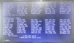
I would also like to know about the I/O Configuration files in F:/UNIT1. The files will have names like IOCFG_C.DAT and IOCFG_Q.DAT. (There might be an IOCFG_B.DAT and/or a IOCFG_D.DAT.) If there is/are IOCFG_R.DAT and/or IOCFG_S.DAT and/or IOCFG_T.DAT that would be helpful to know as well. Use the command:
DIR IOCFG*.DAT
in F:/UNIT1 to show the file date- and time stamps and take a photo of the results and post it to the thread. If you use more than one <I> (and the TMOS HMI) to download and upload to this Mark* V do this for all the operator interfaces that are used for downloading and uploading. Actually, please just do it for all the operator interfaces. [NOTE: We don’t know what unit number this problem Mark V uses, so the unit-specific directory might not be F:/UNIT1….]
Anyway, @White is probably on to something with the jumper settings and I/O termination resistor status. While you’re checking jumper settings please check all the jumper positions on the cards suggested—not just the IONET termination resistor positions.
As for <S> intermittently rebooting, I believe you said <S>’s TCPS card was recently replaced. Check the <S> power supply cable from <PD> to the TCPS to be sure the plugs are all firmly seated, check the TCPS power cable that supplies all the cards in <S> and the <TCDA> in Loc. 2 of <QD1>, and the 3PL cable of <S> as well.
The voting mismatches and the fluctuating signals in <T> are from signals in <P> and <T>’s TCDA in Loc. 5 of <QD1>. AND two of the cards replaced in 2016 were at both ends of <T>’s IONET: the TCQC and the TCDA in Loc. 5 of <QD1>. And <T>’s IONET runs from <T> through the TCEA in Loc. 5 of <P> and ends at the TCDA in <QD1>. If I recall correctly there are IONET termination resistors on the TCEA cards AND on the TCDA cards. What are the chances the IONET termination resistors on either of those cards on <T>’s IONET are not in the correct positions???
Please check ALL the jumper positions on the TCEA in Loc. 5 of <P> and the TCDA of Loc. 3 of <QD1>. Please tell us if any jumpers on these three cards were found out of position.
Unplug ALL of the IONET cables in <T> (on the TCQC, I believe), <P> (the TCEA in Loc. 5) and <QD1> (the TCDA in Loc. 3) and plug them back in several times to loosen/scrape off any oxidation/corrosion on the pins and sockets of the cable connectors and the card connectors. Power down <T> and the TCEA in Loc. 5 (JZ in <P>) before doing this.
DIAGC is notoriously inaccurate because oftentimes when PROMsets were upgraded the required card definition files were not properly updated and those are used by DIAGC to retrieve and display information so if the card definition file doesn’t match the PROMset then the information can be horribly incorrect. (Ask me how I know this…)
I would also like to know about the I/O Configuration files in F:/UNIT1. The files will have names like IOCFG_C.DAT and IOCFG_Q.DAT. (There might be an IOCFG_B.DAT and/or a IOCFG_D.DAT.) If there is/are IOCFG_R.DAT and/or IOCFG_S.DAT and/or IOCFG_T.DAT that would be helpful to know as well. Use the command:
DIR IOCFG*.DAT
in F:/UNIT1 to show the file date- and time stamps and take a photo of the results and post it to the thread. If you use more than one <I> (and the TMOS HMI) to download and upload to this Mark* V do this for all the operator interfaces that are used for downloading and uploading. Actually, please just do it for all the operator interfaces. [NOTE: We don’t know what unit number this problem Mark V uses, so the unit-specific directory might not be F:/UNIT1….]
Anyway, @White is probably on to something with the jumper settings and I/O termination resistor status. While you’re checking jumper settings please check all the jumper positions on the cards suggested—not just the IONET termination resistor positions.
As for <S> intermittently rebooting, I believe you said <S>’s TCPS card was recently replaced. Check the <S> power supply cable from <PD> to the TCPS to be sure the plugs are all firmly seated, check the TCPS power cable that supplies all the cards in <S> and the <TCDA> in Loc. 2 of <QD1>, and the 3PL cable of <S> as well.
1- Checking continuity and insulation of the <S> power cable:
J1 TCPS <S> ------ J1S TCPD <PD>: OK
Cleaning and pluging/unpluging several times, to eliminate possible oxidation or bad contacts, for the connections on <S>: 2PL, JC, 3PL.
2- jumpers check:
TCQC Loc.4 <T>: BJ17 is different from the other Mark Vs (but I think it's for RS232 which we don't use).
TCDA Loc.3 <QD1> : Identical to those of TCDA in Loc. 1 and Loc.2
TCEA Loc.5 <P> : Identical to those of TCEA in Loc. 5 of the other Mark Vs
3- Checking continuity and insulation of the <T> IONET cables (Cleaning and pluging/unpluging several times):
JX TCQC <T> ----- JX1 TCEA Loc.5 <P> : OK
JX2 TCEA Loc.5 <P> ----- JX1 TCDA Loc.3 <QD1> : OK
JRT DTBB <QD1> ----- JR TCDA Loc.3 <QD1> : OK
JQT DTBA <QD1> ----- JQ TCDA Loc.3 <QD1> : OK
4- Checking that all plugs are plugged into all processor cards <T>: OK
After this work, <T> still displays the same vote mismatches. On 2016, When we had changed DCCA, we recovered U9, but we did not format the EEPROM. Could this be the cause of the problem especially it appeared after replacing the cards mentioned before?.
On Monday I will test the cable on <R> : JHR TBQB ----- JH TCQC.
Best regard
It was already suggested to download FORMAT to <T>, perform a hard reboot of <T> reboot, download USER (or ALL—which includes FORMAT & TOTD) ignoring the processor reaching A7 if it reaches A7 before a hard reboot, perform another hard reboot. You will probably need to set the VOTER ID of <T> after formatting the U9 chip. I would also recommend rebooting <Z> (the TCEA in Lic. 5 of <P>) a few minutes after <T> goes to A7 after the second hard reboot since it gets its configuration information from the U9 chip of <T>.
[Don’t worry about downloading an old version of TOTD to <T>. After a little more than an hour the Totalizer data in <T> will get overwritten by the values from the Designated Voter (<R>) so the Totalizer data will be just like the other two control processors after an hour or so.]
It was also recommended to replace the TCDA in Loc. 3 of <QD1>, the DCC of <T> and the TCQC of <T>—ONE AT A TIME, taking care when unplugging the 3PL cable! You might even consider replacing the LCC card.
Please be sure to press FIRMLY all along the tops of the ribbon cable connectors to try to ensure they are not coming apart and are making good contact all along the connectors from side to side.
My other computer isn’t booting up after the MS updates so I’m fighting with that and the manufacturer right now; sorry. That’s where all my Mark* V stuff is stored and I need some of those documents and programs because I don’t have the right font for the CSP in Win11. I’ll keep at it, though. Thanks for the patience.
hello every one,
For the CPD of processor <R> the problem is solved : We found JH TCQC not plugged in, the plug was behind the processor and not visible. After connecting JH, we injected pressure into the 96cd-1 and <R> displays the same value as <S> and <T>.
We did : EEPROM DOWNLOADER>DOWN T1 T USER , next we cut and restarted the power supply of <T> and TCEA Z from <PD>. The <T> prevote display gives the same anomaly and differences of vote.
<S> always restarts by itself.
Best regards
AHNIN,
Thank you for the update.
This is copied and pasted from response #32 to this thread:
The next logical steps in fixing the <T> voter mismatches would be:
a) Replacing the TCDA in Loc. 3 of <QD1>
b) Reformatting the EEPROM of <T> (which effectively erases the EEPROM) followed immediately by re-booting <T> (it should not/will not return to A7), followed by downloading USER to <T> (<T> may jump to A7 after the download—but it’s a false A7!), followed by a hard reboot (using the switch in <PD>) at which time <T> will/should go to A7.
c) Replacing the TCQC of <T>
d) Replacing the LCC of <T>
e) Replacing the DCC of <T>
f) Replacing the TCEA in Loc. 5 of <P>
When replacing the DCC you should reformat the EEPROM (to be sure the EEPROM is erased AND to format the EEPROM to prepare it for the USER download), perform a hard re-boot of <T> (it should not/will not go to A7), download USER to the EEPROM and perform a hard re-boot of <T> which should return the processor to A7.
We're down to this now for <T>. Simply downloading USER to <T> may or may not solve the problem. By reformatting the EEPROM and THEN downloading USER (after rebooting and then rebooting again) effectively erases the EEPROM and re-loads it again with the USER group. If someone ever uploaded from <T> to user-specific files (such as I/O Configuration for example) then the latest and greatest info will not get downloaded because the EEPROM Downloader looks for processor-specific files FIRST and downloads them, and only if it doesn't find processor-specific files does it then download the normal .DAT files. (This was covered in a previous response, with no acknowledgement.)
As for <S>'s intermittent reboot problems, I think you said the TCPS of <S> was very recently replaced (to solve a 125 VDC Battery Ground alarm) and some of the components on TCPS card (electrolytic capacitors if I recall correctly) will degrade over time and can cause nuisance intermittent problems--such as this. Even if the card was properly stored in a temperature- and humidity-controlled location it is STILL possible for some of these components to simply fail because of age. So, if you have another TCPS card, it is recommended you replace it (after doing the same to the cable connectors as was done for <T>).
Again, my thinking was that the discrete (contact) input signals travel over the IONET from the TCDA in Loc. 3 of <QD1> through the TCEA in Loc. 5 of <P> to <T>. And, because there are some signals from the TCEA in Loc. 5 of <P> also that there might be something amiss with the IONET cabling, connectors, receptacles. So, that was the "logic" behind the list and the order of the steps. (If the LED bargraph on the TCEA in Loc. 5 of <P> doesn't flash in the same sequence as the LED bargraphs of all the other TCEAs in <P> then there's some diagnostic condition with the TCEA and it maybe should be replaced sooner rather than at the end of list of suggested steps.
If you don't want to or don't feel replacing the TCPS in <S> is warranted, then try replacing the DCC in <S>. And, possible the LCC, as well. Taking appropriate care with the 3PL cable, of course (as in ANY control processor!).
You have 'A' Mark* V panels--those were the first Mark* V panels produced. DCC and LCC cards were replaced with SDCC and SLCC versions in later Mark* V panels, so those two cards are also older. Any spares available in your warehouse/stores or from any vendor around the world are going to be ... old. Full stop. Period. You may go through more than one card sometimes to find a good one; that's rare but it has happened to me on more than one occasion. And, lots of the cards which are available from vendors have come from Mark* Vs which were removed or replaced with newer control systems--so they were powered-up and in service for who knows how long.
And, from the sounds of it there was never any conductive grease (NyoGel) applied to the ribbon cable connectors and we don't know what kind atmosphere/environment the panels are installed in or near which might contribute to oxidation/corrosion. Cleaner(s) aren't going to prevent oxidation/corrosion like conductive grease will. It's inexpensive and can even be purchased from Amazon last time I checked (about two years ago) and delivered to the site (depending on the location, of course).
You've got two working Mark* Vs, so it should be possible to return this one to a reasonably good working condition. But, age and maintenance are going to be a factor and as we see it's not always straightforward and simple. MANY times problems like this are actually several problems--not just one (as we have already seen with this panel). The Mark* V gets a lot of bad press, some of it deservedly so, some of it not. Unfortunately, the 'A' panels were not as robust as later versions were, but there are still a LOT of them in service.
It's not time to be discouraged. It's never time to be discouraged, actually. Patience and a logic process of troubleshooting--which, as has been said MANY times on Control.com, OFTEN means a process of elimination. Personally, I think we've pretty much eliminated cabling (but not oxidation/corrosion completely) and now we're down to replacing cards. I would prefer to do it one card at a time, but I understand that sometimes "management" doesn't share that sentiment and wants to do everything all at once (which doesn't let anyone know what the cause(s) were). But, this is where you are at. At this point.
WTF, the font for viewing the CSP is MS Linedraw (saw you were having computer issues). I tried attaching but the forum won't allow .TTF file extensions, sorry.
https://learn.microsoft.com/en-us/typography/font-list/ms-linedraw
https://learn.microsoft.com/en-us/typography/font-list/ms-linedraw
Thanks for the link. MSLineDraw works well, but the GE Salem-developed CSP font for Windows document apps is fp_csp.ttf. MS quit supplying MSLineDraw with Windows a few years ago, and it wasn’t readily available on the World Wide Web for at least a couple of years. fp_csp.ttf is usually supplied on most GE Mark* HMIs beginning in the mid-1990s.
I've never tried csp.ttf for Word. I do know I can use linedraw in Notepad and Wordpad (Wordpad recognizes linedraw whereas Word doesn't). Form Wordpad I copy dierctly to Word. Do a little font size adjustments, change colors of the pertinent parts of a big block, etc and now I've got CSP in Word. From there you can save it as html. My fleet has some pretty awesome process alarm help files on my WorkStationST HMIs for Mk V. If GE every gets ahold of them so help me god.Thanks for the link. MSLineDraw works well, but the GE Salem-developed CSP font for Windows document apps is fp_csp.ttf. MS quit supplying MSLineDraw with Windows a few years ago, and it wasn’t readily available on the World Wide Web for at least a couple of years. fp_csp.ttf is usually supplied on most GE Mark* HMIs beginning in the mid-1990s.
"If GE every gets ahold of them so help me god." ???
GE is a mere shell of its former self, as CSA said fairly often. They are not above copying and pasting without attribution, but with their concentration and focus on proprietary information and patents there would be some who would be opposed to "borrowing" from a site.
There's also the NIH aspect of the organization... Not Invented Here. You might have an idea how difficult it was to get GE Salem to use Mark V Studio and to "approve" (grudgingly, by the way) the use of Mark V Studio and the CSP and other documentation tools that were developed by people who didn't work for GE Salem but recognized a need for better documentation that was supplied with the Mark* V. (And, it was only after people in the factory started using the programs/tools that it was, again, grudgingly, approved.)
Anyway, I just wish the original poster would follow the recommendations instead of picking and choosing which ones seem to them to be useful or applicable. This will be the 52nd response to this thread, and while a couple of problems have been solved there's still more serious work to be done, and while it doesn't seem like replacing cards is what's required, there isn't much left to do at this point (except put conductive grease on the cable connectors--which is a practice originated and endorsed by GE Salem); it's not some word of mouth remedy).
Thanks for the help.
I'm sorry WTF for having delayed replacing the cards (I haven't forgotten), but you know, replacing so many new cards from the store then the problem doesn't resolve and ultimately finding the fault in a cable or a supply voltage...
We formatted the EEPROM of <T>, restarted, downloaded USER and restarted as described previously, the problem was not resolved.
Rechecking all plugs and connections of <T>, TCEA Loc.5 <P> and TCDA Loc.3 <QD1>. Everything is OK.
The supply voltages of TCPS <T>, 2PL TCQC, 2PL DCC, JP TCDA Loc.3 <QD1>, J12 and JY DTBA Loc.6 <QD1> were measured. Everything is OK.
Permutation of the JQT-JQ and JQS-JQ wire layers and the <T> voting problem has not been resolved : The cables are OK.
Replacement TCDA Loc.3 <QD1> and TCPS <S>.
We power on the Mark V and the <T> vote becomes normal for almost all signals. But for SVL and SFL2 <T> gives 0 instead of 11 and 50 like <S> and <R>
In addition to the <T> voting problems for SVL and SFL2, we have two other diagnostic alarms which switch between states "0" and "1":
R 275 IOMA power supply out of limits, P24
T 275 IOMA power supply out of limits, P24
For <S> which restarts itself we must check it over time.
Best regard
AHNIN,
Thank you for the update; it is much appreciated. I know; taking a lot of cards all at once out of stores is difficult to justify. That's why I suggest doing it one at a time. I'm VERY PLEASED to hear the discrete (contact) input voting mismatches have been resolved. The DV and SVL issues are coming from <P>. The voltage signals from the station line PTs and the voltage from the generator PTs both pass through <P> (they are terminated on the PTBA in Loc. 6 of <P>). I still don't have access to my Mark* V documents, but you can trace them using the Signal Flow Diagrams in Appendix D of the Mark V Application Manual, GEH-6195 (if I recall correctly). I don't know if they pass through the TCEB and then to the TCEA cards in Loc. 1, -3 and -5, or go directly to the TCEA cards in Loc. 1, -3 and 5. But they are connected to <P> and the TCEA cards use them for synchronization purposes.
As far as the IOMA power supply dithering alarms, that was a problem with early TCPS cards AND with early versions of PROMs used in some of the ‘A’ Mark* V panels. I don't recall if Diagnostic Alarms can be LOCKed or not on some Mark* V <I> operator interfaces. I seem to recall they couldn't be LOCKed in the very early days, but they could be LOCKed in later versions. LOCKing alarms (Process & Diagnostic) Alarms is an overlooked and very useful tool for nuisance alarms (ONLY for verified nuisance alarms, though--or for alarms which can't be resolved without a shutdown and it's important or critical to keep the unit running). The date and time of the LOCKing of ANY alarm(s) should be logged in the Control Log Operator's logbook, as well as the date and time of UNLOCKing of the alarm(s).
The IOMA (I/O MAster) is a couple of PROMs and a lot of electrical components on the DCC that deal with some analog inputs and -outputs. You can look in the I/O Configurator at the IOMA section to see what those signals are. That's about all the help I can offer; it's NOT usually the PROMs that fail, but componets on either the analog I/O terminal boards or the DCC card that cause real problems with the IOMA power supply. Also, cable problems could contribute to the situation.
We haven't talked about this, but panel earthing (grounding) is VERY important. MANY sites were not built with proper earthing systems, OR were built in soils that have corroded and/or eroded the earthing system grid over time (these soils are usually damp, also). Combine this with poor sizing of cables connecting the Mark* V to the earthing system, AND if there are electrical storms (lightning) in the area during some seasons of the year and that's a recipe for lots of nuisance, intermittent--and dithering--alarms, some related to 125 VDC Battery Grounds and others related to analog I/O (especially transmitters and LVDTs and the like). Bad and inconsistent cable shield drain wire grounding practices during construction can also be a problem. Even at sites where multiple machines were installed and commissioned at the same time. These kinds of problems are very difficult to find and resolve because the assumption is always that the construction practices are the same on every machine but unless supervision is good it’s just human nature that people making terminations will use different practices which leads to unusual situations.
Again, this is difficult to find and even more difficult to convince management to devote time and money to. I recall walking past a gas valve module of one of two machines being installed and commissioned at the same time and hearing a very slight high-pitched whining noise for several days (construction was woefully behind schedule and wiring work was still being done during commissioning). I finally got to that gas valve module for loop-checks and found the LVDT wiring for one of the gas valves was improperly terminated to earth. Correcting that problem stopped the whining noise and solved a lot of odd Diagnostic Alarms. Two different construction workers had worked on the electrical terminations in the two gas valve modules.
Everyone is VERY quick to blame the control panel for every problem—but the control panel is connected to field devices and instruments by wires making the control panel one (large and complicated) part of the turbine control system which often is overlooked during troubleshooting after commissioning or even after maintenance outages when devices are disconnected and reconnected.
Anyway progress is being made—after problems which began in 2016…! As my father used to say,“Rome wasn’t built in a single day.” And when alarms have been allowed to persist for weeks, months and even years they can be difficult to troubleshoot and resolve.
Has the machine been started, synchronized and loaded to see if the tripping problem is resolved with the replacement of the TCDA card?
From help_qd and help_bd
0275 ;IOMA POWER SUPPLY OUT OF LIMITS, P24
CAUSE The P24 power supply voltage does not fall inside prescribed limits
(+20 to +32 Vdc). This voltage is measured with a ratiometric
A/D converter that uses P5 as the reference voltage.
EFFECT Potentially bad I/O data. Note, however, that this power supply
drives a lot of I/O cards, so this problem may not be restricted
to just the DCC/SDCC card.
ACTION Since the P5 voltage setting affects the ratiometric A/D input
conversion results, measure the P5 voltage on the DCC/SDCC card.
If necessary, adjust the P5 voltage (as measured on the DCC/SDCC
card) to 5.00 +/-0.01 volts DC by adjusting potentiometer R29
on the TCPS card. If this does not correct the diagnostic, then
check/replace TCPS, JC cable, 1PL cable, or DCC/SDCC card in that
order.
P5 is the reference voltage and can be adjusted at R29 on the TCPS. I've had conversations with some who tweak this a little high when measured at the test points directly on the TCPS card, and some are strict about P5 being exactly 5 when measured in diagnostic counters DIAGC.
Do you have any hard grounds on the 60V float? Should be +60, -60 ~ish, not +100, -20 for example.
Hi @ AHNIN,
I faced a similar problem with one of my frame 6B units (Mark v controller).
every time the unit trips, can start the unit normally, and then the unit will trip after some time (5 to 12 hours time delay) with a "LCC No arcnet communication with (R) &Loss of flame trip" alarm, however later found "R" rebooted automatically it caused a trip the unit.
The "R" core was auto rebooted whenever the LCR door closed strongly by the operation team during their routine inspection and it was found out during my investigation.
later I replaced the TCPS card of the "R" controller and the problem was solved. but clear this issue it took almost 15 days and 13 trips
Yeah, but, ..., the TCPS in <S> was recently replaced, so that cannot be the problem. Right?
We don't know the provenance of the TCPS card which was installed in <S>.
But, @White may have something--again--with adjusting the potentiometer for the IOMA P24 voltage. I have not had to adjust the P24 voltage pot, and I haven't seen this help_qd/help_bd file.
We don't know the provenance of the TCPS card which was installed in <S>.
But, @White may have something--again--with adjusting the potentiometer for the IOMA P24 voltage. I have not had to adjust the P24 voltage pot, and I haven't seen this help_qd/help_bd file.
Hi everyone,
First I will answer your questions:
1- Yes, we have good grounding in the power plant which was checked and renewed about 3 years ago.
2- Yes, alarms can be locked.
3- The machine has not been started, synchronized and loaded. We only opened or shunted certain input contacts (L26AA2, L63FL, L63QAL,...) and we found the prevote of <T> like that of <R> and <S>.
4- Hi White, for <T> we measured the voltages on TCPS which are all within the prescribed limits, especially for P5. For <R>, we have not yet measured. I remind you that the state of these alarms switches between "1" and "0".
5- Hi VSCONTROL, it’s true! we noticed that <S> restarts sometimes when we close the Mark V door.
6- Hi WTF, replacement TCPS was repaired, but the last one is new. So far we haven't found a reboot.
7- Information for WTD: Yes the Help_QD.DAT indicates for diagnostic alarm "275 IOMA ..." that P5 can be adjusted via potentiometer R29 on TCPS.
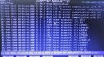
8- We often have LVDT alarms as seen in the attached image. On their connection in TBQC <R> there are no ground wires (only 2 wires).
9- The measurements of the main 125Vdc voltage of the MarK v are as follows:
+ 125Vdc---Ground : +54,3Vdc
- 125Vdc---Ground : -69,2Vdc
Now I'll update you:
Analog signals SVL, DV arrive at PTBA Loc.6 <P> then via JV arrive at TCEB Loc.2 <P> then via JZK arrive at TCEA Loc.5 <P>.
We checked the continuity / insulation of these cables: OK (everything is good).
We swapped the JKZ and JKX files in TCEB Loc.2 <P> without swapping in TCEAs : We have the same problem on <T> for SVL and SFL2.
Note: There is a diagnostic alarm (T 275 IOMA..., P24). We measured the voltage P24 on TCPS <T>: +28.19V stable.
We replaced the TCEA Loc.5 <P> card, but the problem with the SVL and SFL2 values persists in <T>.
First I will answer your questions:
1- Yes, we have good grounding in the power plant which was checked and renewed about 3 years ago.
2- Yes, alarms can be locked.
3- The machine has not been started, synchronized and loaded. We only opened or shunted certain input contacts (L26AA2, L63FL, L63QAL,...) and we found the prevote of <T> like that of <R> and <S>.
4- Hi White, for <T> we measured the voltages on TCPS which are all within the prescribed limits, especially for P5. For <R>, we have not yet measured. I remind you that the state of these alarms switches between "1" and "0".
5- Hi VSCONTROL, it’s true! we noticed that <S> restarts sometimes when we close the Mark V door.
6- Hi WTF, replacement TCPS was repaired, but the last one is new. So far we haven't found a reboot.
7- Information for WTD: Yes the Help_QD.DAT indicates for diagnostic alarm "275 IOMA ..." that P5 can be adjusted via potentiometer R29 on TCPS.
8- We often have LVDT alarms as seen in the attached image. On their connection in TBQC <R> there are no ground wires (only 2 wires).
9- The measurements of the main 125Vdc voltage of the MarK v are as follows:
+ 125Vdc---Ground : +54,3Vdc
- 125Vdc---Ground : -69,2Vdc
Now I'll update you:
Analog signals SVL, DV arrive at PTBA Loc.6 <P> then via JV arrive at TCEB Loc.2 <P> then via JZK arrive at TCEA Loc.5 <P>.
We checked the continuity / insulation of these cables: OK (everything is good).
We swapped the JKZ and JKX files in TCEB Loc.2 <P> without swapping in TCEAs : We have the same problem on <T> for SVL and SFL2.
Note: There is a diagnostic alarm (T 275 IOMA..., P24). We measured the voltage P24 on TCPS <T>: +28.19V stable.
We replaced the TCEA Loc.5 <P> card, but the problem with the SVL and SFL2 values persists in <T>.
Attachments
-
140.4 KB Views: 11
@AHNIN,
Thank you for the update.
SVL (Station Voltage-Line) is the voltage signal from the Running (Bus) PTs of the system the machine will be trying to synchronize with. SFL1 and SFL2 (Station Frequency-Line 1 and -2) are frequency signals derived from the Running (Bus) PTs (from the SVL signal).
An LVDT usually has four leads, and they are divided into two twisted, shielded pair cables, one twisted, shielded pair for the "excitation" (power) source for the LVDT, and one twisted, shielded pair for the feedback signal from the LVDT. The excitation comes from <R> or <S> or <T> (so that there is redundancy in the excitation in case one control processor has to be shut down or has no output while the unit is running), and the excitation is also connected to an I/O terminal board on <R>. Each LVDT of the pair of LVDTs on a servo-operated device will get LVDT excitation from separate control processors (so, for example, one might get excitation from <R> and the other might get excitation from <T>). The feedback signal is then "fanned out" (sent to all three control processors) from the I/O terminal board of <R>. That's why you're seeing only two terminations per LVDT feedback--because you're looking at only one twisted, shielded pair of the two that are necessary for the LVDT to produce a feedback signal. So, each LVDT of a pair of LVDTs gets (or is supposed to get) it's excitation from a different control processor, and ALL LVDT feedback signals are connected to an I/O terminal board on <R> and "fanned out" to the three control processors. So, you should see four (4) LVDT feedback signals terminated on the I/O terminal board of <R>, to the 5th and 6th LVDT inputs and to the 10th and 11th LVDT inputs of that I/O terminal board (two wires per LVDT for a total of eight wires).
If I recall correctly from the IO.ASG file you sent, SVO3 is the liquid fuel bypass valve servo output, and SVO5 is the IGV servo output. It would make sense that when there were other voting mismatches (so, before you replaced the TCDA) that <T> was NOT participating in controlling fuel or IGVs when the unit was running. Are you still seeing this problem with the two servo output signals after replacing the TCDA of <T> AND when the unit is NOT running? If this is true, can you take pictures of the AutoCalibrate screens for SVO3 and SVO5 and post them to this thread? (You don't have to enable AutoCalibrate--just take pictures of the pages when the voting mismatches and servo current disagreements occur--clear photos, please.)
I thought that before you swapped the cables on the TCEB in <P> the voting mismatches were on DV and SVL--and now you're saying the voting mismatches are on SVL and SFL2. BUT, if <T> is still indicating PT voltage voting mismatches after swapping the cables from TCEB to the TCEA in Loc. 5 of <P> at the TCEB, then it would seem that the problem is the TCEA in Loc. 5 of <P>. AND, there might also be a problem with the TCEB in Loc. 2 of <P>. 'Cause I'm getting a little confused here.... This will be the 60th response to this thread....
Anyway, thanks for the feedback and your patience. I have this feeling there is just some small thing we don't know that is at the root cause of these problems--like a very serious 125 VDC Battery Ground, or a lightning strike (or strikes) or an earth grid issue (it's not normal for plants to test and "renew" the existing earth grid). But, it is what it is, right?
Again, there has been an unusual amount of attention paid to the "IOCFG FAILED" message during the boot-up sequence of processors. That's a bad message, for sure, but it's NOT abnormal, especially for older Mark* V panels and PROMsets. It's been said that the other Mark* Vs on the site experience the same messages during boot-up and they reach A7 and there aren't any complaints about them. Now, there is a complaint about LVDT problems and servo current mismatches--but we don't know if they are still occurring after the TCDA change or not. The date/time of the alarms indicates that <C> was rebooted and the current (correct) time has not been sent to the Mark* V.
This is what happens when alarms--Process AND Diagnostic--are allowed to exist for weeks, months, years, and then, all of a sudden it becomes a problem and needs to be solved NOW. As has been experienced in this thread for this machine, there are multiple problems which are contributing to the unreliability of the machine, and we just don't really know enough about the operation, maintenance and troubleshooting of this machine over time (years, apparently!). AND, there is an attention to "problems" which probably don't apply as they are normal (as has been proven) and we don't precisely when these latest alarms started or how long they have existed.
We are trying to help, but we need more details. And, frankly, sometimes the story seems to change (ever so slightly). I've been doing this for a LONG time, so I get it--but, again, to anyone following this thread: DON'T LET ALARMS JUST FESTER AND PERSIST FOR WEEKS, MONTHS AND ESPECIALLY FOR YEARS and then all of a sudden decide it's time to fix "THE problem" because it more than likely isn't going to be one problem, it's going to be multiple problems, and it's going to take time to work through each one. Especially because we don't know the history of the unit since the first problem (and we don't even really know the first problem...!).
We'll keep trying, but it's slow going on problems like this.
And, I gotta say--for the LAST time--failure to apply conductive grease on connectors IS NOT helping anything. I've heard it MANY times, "Conductive grease will cause shorts and grounds!" but it DOESN'T if applied properly.
Anyway, we await more information and clear pictures.