Facebook
 Google
 GitHub
 Linkedin
i am a mechanical engineer working in power generating plant bryton cycle , we are using gas turbine frame 6b .
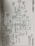
i try to study the diagrams for the unit but as a mechanical engineer there are alot of instrumentaions devises that i dont knew how its so simply i google it and understand it but some times and some diagrams there are things only expertise people knew .
my question is , as i study the units if i post the P&ID for ex: IGV etc... will you give me quick or basic explanation about it ? because i am not seen this happened here before on control.com .
best regards .