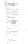
I'm having trouble writing a ladder logic diagram for these sfcs

I'm having trouble understanding how i should write the ladder logic diagram for these two SFCs. I have a routine for edge detection and another for the start stop logic, and the SFCs work correctly as routines in the main routine. I'm just really not sure why I don't know where to begin with the conversion. The example that I'm given looks like the sfc on the one side and the conversion on the other. maybe that's whats confusing me?
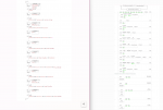
example conversions.png
Example conversions

sfcs to be converted:
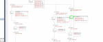
sorting sfc.png
sfc.png
 
your picture is blur and unreadable, but from the format looks it is come from Rockwell Automation software : RSlogix 5000 or Studio 5000 , basically you can convert each pair of TRANS and STEP at SFC to become one Rung or more in Ladder, Tags and logic expression from TRANS will be ladder Inputs element and Tags and logic expression from STEP as outputs element.
 
your picture is blur and unreadable, but from the format looks it is come from Rockwell Automation software : RSlogix 5000 or Studio 5000 , basically you can convert each pair of TRANS and STEP at SFC to become one Rung or more in Ladder, Tags and logic expression from TRANS will be ladder Inputs element and Tags and logic expression from STEP as outputs element.
thank you so much!
 
Top