Industrial Compressor Circuit Diagram Help

Hi everyone,I was gifted a 350-liter industrial air compressor (CompAir Marshall Branson 2000, UK). The previous owner had already started working on it, and I’m now trying to put everything back the way it was originally.

I’m not an industrial electrician, but I do have some basic electronics knowledge. I would really appreciate some guidance from someone who has experience with this kind of equipment.

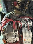
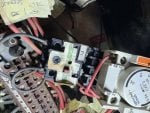
From what I’ve been able to research so far, it looks like the system uses, a 3 way switch, a star–delta starter with an overload relay and three timers. I’m especially curious why three timers are used?

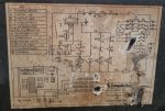
Before I start reconnecting the circuit, I’d love to better understand how the electrical system is meant to work. I’ve included a reference showing how the wiring was before it was dismantled.

Thanks so much for your time and any help you can offer!

525494442_2100310190495755_8596675581731460106_n.jpg

Facebook_creation_2ABFF1AB-1789-44D0-804D-023439708173.jpeg


526818900_4280165115551137_7606501630882430488_n.jpg


Attachments

The ROT device is operated by the pressure switch, so I suspect it's doing something with unloading or turning the unit off after a time of being at pressure. The other timers look like they're built into the line/star/delta contactor assembly and will handle the star-delta starter sequencing. When it's first started, it will pull in the contactors so that the motor is connected in a star arrangement for better starting torque/current characteristics. After a time, it switches the motor to delta for normal full speed operation.
 
The ROT device is operated by the pressure switch, so I suspect it's doing something with unloading or turning the unit off after a time of being at pressure. The other timers look like they're built into the line/star/delta contactor assembly and will handle the star-delta starter sequencing. When it's first started, it will pull in the contactors so that the motor is connected in a star arrangement for better starting torque/current characteristics. After a time, it switches the motor to delta for normal full speed operation.
Hi Joseph,
Thanks a lot for the detailed explanation, it tackles a lot of questions. I have a few more questions. i need clarity which of the timers is the ROT? Also after P.SW we see the line (5) is connecting to the D contactor K2, is this connecting to the add block (TA1 DN 11) NO rather than the actual contactor itself?
 
My first guess would be the Omron timer, but I don't know for sure without having hands on the system.

When P/SW is closed, the coil of ROT is energized. When K2 is also closed (motor is running at speed, wired Delta), SV will energize. I don't know what SV controls, but it's likely the load/unload control.

Terminals 23 and 24 of K2 are a Normally Open (NO) auxiliary contact that's closed when K2 (Delta) is closed, which happens after a time delay after the motor is started.
 
Looks like the 3 way switch is for Hand or Auto. In Hand mode the compressor keeps running, only the load solenoid is turned off once the pressure is reached. In Auto the motor is turned off if the pressure is reached and does not drop again during the Run On Time. The other timers are pneumatic timers that have their delay after the electrical contactor is energised for K1T and de-energised for K3T. K1T is to switch from star to delta. K3T is to make sure the star timer has definitely opened before closing the delta contactor - don’t want these two on at the same time, otherwise big bang shorting three phases.
 
Top