Facebook
 Google
 GitHub
 Linkedin
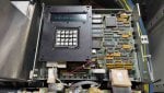
Recently in our GT (FR6B), the maintenance team replaced the starting diesel engine VR-13 and adjusted the governor. After restarting the unit, during startup, it tripped on an overspeed alarm(the unit did not even reach 2% speed), and the HMI behaved strangely. Consequently, the maintenance team decided to reboot the C core. However, after the hard reboot, the C core did not revert to A7 but remained at A6.
The following actions were taken:
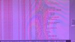
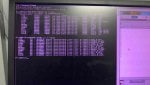
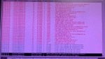
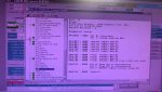
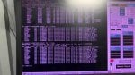
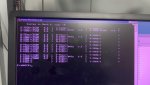
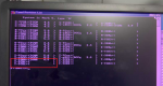
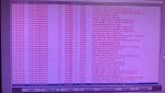
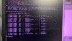
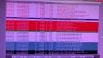
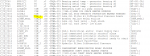
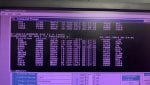
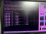
LCC alarms(6 DCC ERRORS);
The following actions were taken:
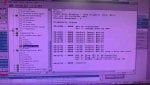
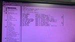
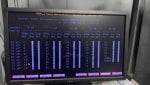
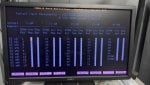
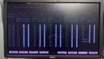
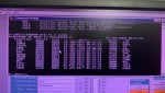
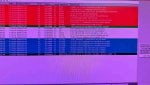
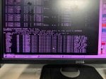
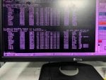
- Checked the IO states of all cards using LCC, all were in A6.
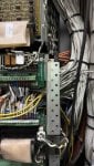
- Inspected all ribbon cables; no abnormalities were found.
- Card_ID.exe checked with IO configurator and all are the same
- Attempted "EEPROM DOWN T3 C ALL" and rebooted, but C core remained at A6.
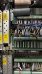
- Replaced the TCPS card with a new one, but the C core stayed at A6.
- Replaced TCCA card with a new one, result remained at A6.
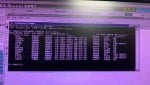
- Swapped SDCC card from D core (C EEPROM chip replaced), which allowed C core to reach A7, but the LCC display showed "D-A7_22% 16.03.26" and the HMI remained inactive.
- Tested the C core SDCC card in D controller; it stayed at A6 (LCC displayed -C instead of D).
- as of now, we don't have a new SDCC card we have only -DS200SDCCG5
LCC alarms(6 DCC ERRORS);
- QST DPM TIMEOUT
- MISSING IO CARD
- IO CFG BAD RESP
- IO CFG FAILED
- DCC IO RESET
Attachments
-
 48.9 KB Views: 13
 -
 48.8 KB Views: 13
 -
 48.1 KB Views: 12
 -
 49.1 KB Views: 14
 -
 49.5 KB Views: 11