Modbus registers

Hi

I'm new to the modbus registers and trying to learn about how to read them.

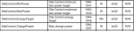
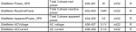
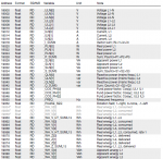
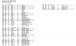
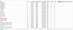
i have some basic questions that i am trying to prepare a modbus registers template in csv file which is received from a product manufacturer in pdf file explaining the modbus addresses and data type unit ( attached file for the reference).

1- How can i know that this address is Holding/input/coil/ ? bcz as per my understanding addresses from 30001-39999 are input registers , 40001-49999 are holding registers. but how you call the 19020, 19070 as holding register ? Should not be call as discrete input register as 19020 falls in the range of 10001-19999 ?

How can i know that the data is 32 bit or 16 bit ?

How can i know that this register has the decimal (2) and (0) ? Can anyone explain what is the decimal here ?

Thankyou
 

Attachments

0x = Coil = 00001-09999 1x = Discrete Input = 10001-19999 3x = Input Register = 30001-39999
4x = Holding Register = 40001-49999

You stated bcz as per my understanding addresses from 30001-39999 are input registers , 40001-49999 are holding registers. but how you call the 19020, 19070 as holding register ? Should not be call as discrete input register as 19020 falls in the range of 10001-19999 ?

Where you see holding registers..on the attached document...
 
its wide; however, there is a widely used de facto standard for reading and writing data wider than 16 bits. The most common are IEEE 754 floating point, and 32-bit integer. The convention may also be extended to double precision floating point and 64-bit integer data.

The wide data simply consists of two consecutive "registers" treated as a single wide register. Floating point in 32-bit IEEE 754 standard, and 32-bit integer data, are widely used. Although the convention of register pairs is widely recognized, agreement on whether the high order or low order register should come first is not standardized. For this reason, many devices, including all Control Solutions gateways, support a "swap" option. This means you simply check the "swapped" option if the other device treats wide data in the opposite order relative to Control Solutions default order. In some cases, the “swap” option is more explicitly identified as “high order data is in first register” or something to that effect.

Most Control Solutions Modbus products default to placing the high order register first, or in the lower numbered register. This is known as "big endian", and is consistent with Modbus protocol which is by definition big endian itself. The byte order for all 16-bit values is most significant byte first.

 
There are multiple ways that vendors document Modbus registers. The register "reference" designation (i.e. the 4X/40000, 3X/30000, 1X/10000, 0x/00000) may or may not be included. In addition, there is also 1-based addressing and 0-based addressing. When the reference designation is used, 1-based addressing is always used. When 0-based addressing is used, the address may be provided in either decimal or hexadecimal. Hexadecimal addresses are almost always 0-based.

For example, here are the common ways that Holding Register 1234 can be documented:

With Reference Designation (1-Based Addressing)
41234

Without Reference Designation (1-Based Addressing)
1234

Without Reference Designation (0-Based Addressing, Decimal)
1233

Without Reference Designation (0-Based Addressing, Hexadecimal)
0x04D1

From your attachment, it seems like your Modbus device may be a Janitza UMG 96-PA. In its Modbus manual (https://www.janitza.com/manuals.htm...PA/firmware-v1/janitza-mal-umg96pa-fw1-en.pdf) there is a note about the supported Modbus Functions. The device supports reading both Holding Registers (Function Code 03) and Input Registers (Function Code 04). So I believe the registers can be accessed either as Holding Registers or Input Registers and the register list is provided without the reference designation.

Additionally, in the "Byte sequence" section, it tells you that the register data is ordered in Big-Endian format - meaning that for 32-bit values (i.e. int, uint, float) the first register address containes the most-significant 16-bits and the next register address contains the least-significant 16-bits. Note that, in Modbus, 32-bit values take up 2 16-bit registers (i.e. 2 register addresses are used).

The "Number formats" section tells you the data type of each parameter (from the Format column in the register list). This tells you whether it is 16-bit, 32-bit, etc.

Now the only unknown is whether this devices uses 1-based addressing or 0-based addressing. Therefore, you will need to perform testing to figure out which addressing method is used (you will also need to know which addressing method is used by your Modbus master).
 
1. >1- How can i know that this address is Holding/input/coil/ ?

Answer: The map shows a Read/Write column. The portion you included shows only read-only values, but the fact that the choice is indicated indicates that these are most likely Holding Register values. Input Registers are, by definition, read-only values, meaning a master/client cannot write a value to an Input Register. The vendor determines whether Holding Registers are Read or Write values.

The fact that the data value format is 'float', which means an IEEE754 32 bit floating point value, tells you that these are not input bits or coils.

2. >40001-49999 are holding registers. but how you call the 19020, 19070 as holding register ?

Answer A: The leading numeral 4 in 40001 is not part of the Modbus message. It is an indicator to human beings as to which of four memory areas the address belongs to: Coil (0), DI (1), Holding (4) or Input Register (3). The digits following the leading numeral are one-based decimal values. My convention is to put brackets around the leading numeral to separate it from the one-based register value: (4)0001.

Answer B: As you read through the addresses in your attached memory map, you can determine that they are NOT hexadecimal, they are decimal addresses (..08 is followed by ..10, not ..A). Decimal addresses are always one-based, starting at (4)0001, whereas hexadecimal addresses are always zero-based, starting the address at zero: 0000, 0001, 0002.

There is never a (4)0000 address, because the use of the leading numeral (4) indicates decimal, one-based register addressing, one-based starts at (4)0001.

Answer C: 19020?

5-digit vs 6-digit addressing.

The two byte 16 bit word used for register addressing by Modbus can technically cover a range of 65536 register addresses.

In the olden days, the limited memory available used only 9999 register addresses of the possible 65536 potential register addresses for each of the groups, DI', Coils, Holding Registers, Input Registers. That's known as 5-digit addressing (the leading numeral plus 4 decimal digits maxing out at 9999).

Your cited Holding register range (4)0001 through (4)9999 is an example of 5-digit addressing within the restricted range of 9999 register addresses.

As the cost of memory dropped in the late 1990's, vendors started supporting the full range of 65536 register addresses: for example, (4)00001 through (4)65536 or 0x0000 through 0xFFFF. These are known as 6-digit addresses: the leading memory area numeral plus 5 decimal digits.

The cited addresses in your attached Modbus memory map are 6-digit addresses:
19020 = (4)19020
19070 = (4)19070

3. >Should not be call as discrete input register as 19020 falls in the range of 10001-19999 ?

(4)19020 is the "real power L1" value.

The (1)0001-(1)9999 range is for coils, which are discrete, a logic 1 or a logic 0.

Is your L1 real power value a coil state with a logic 1 or a logic 0? Probably not.

19020 is (4)19020, the first part of a floating point value that requires (two) Holding registers, (4)19020 and (4)19021, each with 16 bits of the 32 bit floating point value.

4. >How can i know that this register has the decimal (2) and (0) ? Can anyone explain what is the decimal here ?

Answer: I am not quite sure what you are asking here. If you are asking why the register values increment by two, it's because a 32 bit floating point value requires two 16 bit Modbus registers.

5. Dealing with the master:

Many times it is unclear what the master/client expects for target register/addresses.
Some use the leading numeral and one-based indexed address value.
Some let you pick a memory area and then only want the one-based indexed value
Some let you pick a memory area and want hexadecimal zero-based addresses
Some want a function code and the indexed address
And there are others that don't come to mind at the moment.

Frequently, it's not explained well and requires some experimentation to figure it out.
 
There are multiple ways that vendors document Modbus registers. The register "reference" designation (i.e. the 4X/40000, 3X/30000, 1X/10000, 0x/00000) may or may not be included. In addition, there is also 1-based addressing and 0-based addressing. When the reference designation is used, 1-based addressing is always used. When 0-based addressing is used, the address may be provided in either decimal or hexadecimal. Hexadecimal addresses are almost always 0-based.

For example, here are the common ways that Holding Register 1234 can be documented:

With Reference Designation (1-Based Addressing)
41234

Without Reference Designation (1-Based Addressing)
1234

Without Reference Designation (0-Based Addressing, Decimal)
1233

Without Reference Designation (0-Based Addressing, Hexadecimal)
0x04D1

From your attachment, it seems like your Modbus device may be a Janitza UMG 96-PA. In its Modbus manual (https://www.janitza.com/manuals.htm...PA/firmware-v1/janitza-mal-umg96pa-fw1-en.pdf) there is a note about the supported Modbus Functions. The device supports reading both Holding Registers (Function Code 03) and Input Registers (Function Code 04). So I believe the registers can be accessed either as Holding Registers or Input Registers and the register list is provided without the reference designation.

Additionally, in the "Byte sequence" section, it tells you that the register data is ordered in Big-Endian format - meaning that for 32-bit values (i.e. int, uint, float) the first register address containes the most-significant 16-bits and the next register address contains the least-significant 16-bits. Note that, in Modbus, 32-bit values take up 2 16-bit registers (i.e. 2 register addresses are used).

The "Number formats" section tells you the data type of each parameter (from the Format column in the register list). This tells you whether it is 16-bit, 32-bit, etc.

Now the only unknown is whether this devices uses 1-based addressing or 0-based addressing. Therefore, you will need to perform testing to figure out which addressing method is used (you will also need to know which addressing method is used by your Modbus master).
Thank you so much for the detailed explanation. It will help me a lot for future
 
1. >1- How can i know that this address is Holding/input/coil/ ?

Answer: The map shows a Read/Write column. The portion you included shows only read-only values, but the fact that the choice is indicated indicates that these are most likely Holding Register values.

The fact that the data value format is 'float', which means an IEEE754 32 bit floating point value, tells you that these are not input bits or coils.

2. >40001-49999 are holding registers. but how you call the 19020, 19070 as holding register ?

Answer A: The leading numeral 4 in 40001 is not part of the Modbus message. It is an indicator to human beings as to which of four memory areas the address belongs to: Coil (0), DI (1), Holding (4) or Input Register (3). The digits following the leading numeral are one-based decimal values. My convention is to put brackets around the leading numeral to separate it from the one-based register value: (4)0001.

Answer B: As you read through the addresses in your attached memory map, you can determine that they are NOT hexadecimal, they are decimal addresses (..08 is followed by ..10, not ..A). Decimal addresses are always one-based, starting at (4)0001, whereas hexadecimal addresses are always zero-based, starting the address at zero: 0000, 0001, 0002.

There is never a (4)0000 address, because the use of the leading numeral (4) indicates decimal, one-based register addressing, one-based starts at (4)0001.

Answer C: 19020?

5-digit vs 6-digit addressing.

The two byte 16 bit word used for register addressing by Modbus can technically cover a range of 65536 register addresses.

In the olden days, the limited memory available used only 9999 register addresses of the possible 65536 potential register addresses for each of the groups, DI', Coils, Holding Registers, Input Registers. That's known as 5-digit addressing (the leading numeral plus 4 decimal digits maxing out at 9999).

Your cited Holding register range (4)0001 through (4)9999 is an example of 5-digit addressing within the restricted range of 9999 register addresses.

As the cost of memory dropped in the late 1990's, vendors started supporting the full range of 65536 register addresses: for example, (4)00001 through (4)65536 or 0x0000 through 0xFFFF. These are known as 6-digit addresses: the leading memory area numeral plus 5 decimal digits.

The cited addresses in your attached Modbus memory map are 6-digit addresses:
19020 = (4)19020
19070 = (4)19070

3. >Should not be call as discrete input register as 19020 falls in the range of 10001-19999 ?

(4)19020 is the "real power L1" value.

The (1)0001-(1)9999 range is for coils, which are discrete, a logic 1 or a logic 0.

Is your L1 real power value a coil state with a logic 1 or a logic 0? Probably not.

19020 is (4)19020, the first part of a floating point value that requires (two) Holding registers, (4)19020 and (4)19021, each with 16 bits of the 32 bit floating point value.

4. >How can i know that this register has the decimal (2) and (0) ? Can anyone explain what is the decimal here ?

Answer: I am not quite sure what you are asking here. If you are asking why the register values increment by two, it's because a 32 bit floating point value requires two 16 bit Modbus registers.

5. Dealing with the master:

Many times it is unclear what the master/client expects for target register/addresses.
Some use the leading numeral and one-based indexed address value.
Some let you pick a memory area and then only want the one-based indexed value
Some let you pick a memory area and want hexadecimal zero-based addresses
Some want a function code and the indexed address
And there are others that don't come to mind at the moment.

Frequently, it's not explained well and requires some experimentation to figure it out.
Thanks David for your detailed and informative response, I will keep asking the similar kind of basic questions.
 
Thanks David for your detailed and informative response, I will keep asking the similar kind of basic questions.
Hi again,

As i mentioned in the earlier questions that i am preparing a template in csv format. Attached are files for the references, in the csv format i want to mention that the value has decimal or not ( 0 or 2 ) but i dont know the basic that how to understand this that the value has decimal or not ?

And also can you please explain the offset and scaling with numbers specially here ?

It will be grateful if anyone can fill / reply with values may be 4,5 rows in decimal columns with explanation for my understanding and knowledge ?

Thank you
 

Attachments

Please clarify what you mean by "value has decimal or not".
Do you mean like this definition? " In algebra, a decimal number can be defined as a number whose whole number part and the fractional part is separated by a decimal point. "
As all variables in your screenshots have "Data type"=float and each of them takes 2 registers (4 bytes), the are all 32-bit floating-point numbers. So e.g. "Voltage L1-N" can have value 220, but it can also have value 220.543 (or, more probably, only 220.5, because that accuracy would be too costly).

If you mean anything else, please explain further :)
 
I think the Decimals column just means how many places after the decimal you want to see in your display, HMI, etc. This is a preference of how you want to see the value. It is completely up to you what you set this field to.

Using Peter's example, if the "Voltage L1-N" has a value of 220.543, the following would be the effects of different Decimals settings:

Decimal = 0
220

Decimal = 1
220.5

Decimal = 2
220.54

Decimal = 3
220.543
 
Most of the values on your slave map are floating point values, so they can be displayed as decimal formats like ±XX.xxxxxx or ±XXXXXX.xxxxx, or scientific notation: 3.498523 X 10^-6

The purpose of Modbus is to get binary values representing something or other from one end to other (slave to master).

When that 'something' is a floating point value (or an integer)
- Modbus can carry a polarity bit
- Modbus does not know or care about engineering units.
- Modbus does not know or care about scaling values
- Modbus does not know about tag names

It's up to the HMI function (not Modbus) to format the raw Modbus data that gets 'displayed'.

To cope with the fact that Modbus just transfers binary bits and does not deal with other critical aspects like engineering units, tag names and scaling values, people create a tag database for both control and HMI purposes.

Your spreadsheet looks similar to the tag databases I've created. There are columns in the spreadsheet related to how the HMI displays the value(s); (in my projects, control functions typically use the raw floating point values). For HMI purposes, factors like significant digits, scaling factors and engineering units play a role.

Do all six digits to the right of the decimal point in the value 271.737421 volts have any meaningful significance? Maybe the first two do, maybe even three, but the 5th and 6th? Unlikely. But the answer is not absolute; it is application-specific. How many significant digits should displayed value use? Most HMI products, whether HMI panels, SCADA or DCS software nowadays seem to allow for truncating a floating point value to a given number of digits to the right of the decimal point, without a lot bit banging to get there.

It is typical to encounter integer formatted data that needs to scaled/multiplied by 0.10 or 0.01 or 0.001 in order to convert a whole number integer in the Modbus register into a decimal formatted process value.

It looks to me like your 'decimal' column is the number of digits you want to see to the right of the decimal point in an HMI representation of the Modbus data as a digital value or in trend graph, bar graph or meter display. I can't help you with that, it's specific to your application.
 
I think the Decimals column just means how many places after the decimal you want to see in your display, HMI, etc. This is a preference of how you want to see the value. It is completely up to you what you set this field to.

Using Peter's example, if the "Voltage L1-N" has a value of 220.543, the following would be the effects of different Decimals settings:

Decimal = 0
220

Decimal = 1
220.5

Decimal = 2
220.54

Decimal = 3
220.543

Now it is clear to me. Thanks
 
Most of the values on your slave map are floating point values, so they can be displayed as decimal formats like ±XX.xxxxxx or ±XXXXXX.xxxxx, or scientific notation: 3.498523 X 10^-6

The purpose of Modbus is to get binary values representing something or other from one end to other (slave to master).

When that 'something' is a floating point value (or an integer)
- Modbus can carry a polarity bit
- Modbus does not know or care about engineering units.
- Modbus does not know or care about scaling values
- Modbus does not know about tag names

It's up to the HMI function (not Modbus) to format the raw Modbus data that gets 'displayed'.

To cope with the fact that Modbus just transfers binary bits and does not deal with other critical aspects like engineering units, tag names and scaling values, people create a tag database for both control and HMI purposes.

Your spreadsheet looks similar to the tag databases I've created. There are columns in the spreadsheet related to how the HMI displays the value(s); (in my projects, control functions typically use the raw floating point values). For HMI purposes, factors like significant digits, scaling factors and engineering units play a role.

Do all six digits to the right of the decimal point in the value 271.737421 volts have any meaningful significance? Maybe the first two do, maybe even three, but the 5th and 6th? Unlikely. But the answer is not absolute; it is application-specific. How many significant digits should displayed value use? Most HMI products, whether HMI panels, SCADA or DCS software nowadays seem to allow for truncating a floating point value to a given number of digits to the right of the decimal point, without a lot bit banging to get there.

It is typical to encounter integer formatted data that needs to scaled/multiplied by 0.10 or 0.01 or 0.001 in order to convert a whole number integer in the Modbus register into a decimal formatted process value.

It looks to me like your 'decimal' column is the number of digits you want to see to the right of the decimal point in an HMI representation of the Modbus data as a digital value or in trend graph, bar graph or meter display. I can't help you with that, it's specific to your application.

Thank you so much for the detailed answer
 
Please clarify what you mean by "value has decimal or not".
Do you mean like this definition? " In algebra, a decimal number can be defined as a number whose whole number part and the fractional part is separated by a decimal point. "
As all variables in your screenshots have "Data type"=float and each of them takes 2 registers (4 bytes), the are all 32-bit floating-point numbers. So e.g. "Voltage L1-N" can have value 220, but it can also have value 220.543 (or, more probably, only 220.5, because that accuracy would be too costly).

If you mean anything else, please explain further :)
Thankyou for your answer
 
Hi all,

I am here again with basic question, literally i am learning a lot with help of you guys. Thanks for teaching me the basics

How can i know that the data type is signed or unsigned ( S32 U32, S16 ,U16 ) ?
For example i have modbus addresses 1040, 1042, 1044 & 401, 403, 405, 407 in the attached files but how i know which is Signed and which is unsigned ?

Thanks for your cooperation
 

Attachments

The 5th column in your images tells you the data type. For all of the registers you show, the data type is "int32".

Typically "int32" means signed 32-bit integer and "uint32" means unsigned 32-bit integer. There should be a section in the device's manual that explains each data type.
 
The implication of a 32 bit value is that the master has to read two 16 bit Modbus registers in order to get the entire data value.

One exception - I do remember running into a slave that did allow the master to read the low order 16 bit word only (data type = 32 bit INT), without throwing an exception code, which was handy because the values of interest were only 3 or 4 significant digits that did not need 32 bits of resolution, easily resolved with just the low order 16 bits.
 
Top