Motor HP at No-Load

C

Thread Starter

Chris

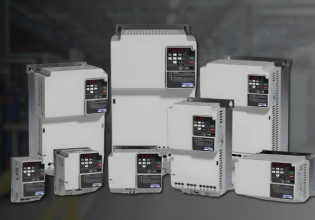
I'm purchasing a VFD with the sole purpose of running the motor at no-load so I don't want to spend more than I have to on a drive. The PMM is 300HP and needs to go through some testing where it will be operated only at no-load. Are there any good equations out there that are good enough for estimating what size drive I need?
 
Chris... it might be more economical to purchase a motor, sized for duty-cycle, rather than one having a lower than normal No-load excitation current.

Regards, Phil Corso
 
> Sizing VFDs for the load

How do you size a VFD drive for an application and feel confident it's going to work? First, you must understand the requirements of the load. It helps also if you understand the difference between horsepower and torque. As electrical people, we tend to think of loads in horsepower ratings instead of torque ratings. When was the last time you sized something based on torque? Thus, both torque and horsepower must be carefully examined.

Torque. Torque is an applied force that tends to produce rotation and is measured in lb-ft or lb-in. All loads have a torque requirement that must be met by the motor. The purpose of the motor is to develop enough torque to meet the requirements of the load.

Actually, torque can be thought of as "OOUMPH". The motor has to develop enough "OOUMPH" to get the load moving and keep it moving under all the conditions that may apply.

Horsepower. Horsepower (hp) is the time rate at which work is being done. One hp is the force required to lift 33,000 lbs 1 ft in 1 min. If you want to get the work done in less time, get yourself more horses!

Here are some basic equations that will help you understand the relationship between hp, torque, and speed.

hp = (Torque x Speed)/5250 (eq. 1)

Torque = (hp x 5250)/Speed (eq. 2)

As an example, a 1-hp motor operating at 1800 rpm will develop 2.92 lb-ft of torque.

Know your load torque requirements Every load has distinct torque requirements that vary with the load's operation; these torques must be supplied by the motor via the VFD. You should have a clear understanding of these torques.

* Break-away torque: torque required to start a load in motion (typically greater than the torque required to maintain motion).

* Accelerating torque: torque required to bring the load to operating speed within a given time.

* Running torque: torque required to keep the load moving at all speeds.

* Peak torque: occasional peak torque required by the load, such as a load being dropped on a conveyor.

* Holding torque: torque required by the motor when operating as a brake, such as down hill loads and high inertia machines.

Practical know how guidelines

The following guidelines will help ensure a correct match of VFD and motor.

1. Define the operating profile of the load to which the VFD is to be applied. Include any or all of the "torques" discussed above. Using a recording true rms ammeter to record the motor's current draw under all operating conditions will help in doing this. Obtain the highest "peak" current readings under the worst conditions. Also, see if the motor has been working in an overloaded condition by checking the motor full-load amps (FLA). An overloaded motor operating at reduced speeds may not survive the increased temperatures as a result of the reduced cooling effects of the motor at these lower speeds.

2. Determine why the load operation needs to be changed. Very often VFDs have been applied to applications where all that was required was a "soft start" reduced voltage controller. The need for the VFD should be based on the ability to change the load's speed as required. In those applications where only one speed change is required, a VFD may not be necessary or practical.

3. Size the VFD to the motor based on the maximum current requirements under peak torque demands. Do not size the VFD based on horsepower ratings. Many applications have failed because of this. Remember, the maximum demands placed on the motor by the load must also be met by the VFD.

4. Evaluate the possibility of required oversizing of the VFD. Be aware that motor performance (break-away torque, for example) is based upon the capability of the VFD used and the amount of current it can produce. Depending on the type of load and duty cycle expected, oversizing of the VFD may be required.

Key VFD specifications

While there are many specifications associated with drives, the following are the most important.

* Continuous run current rating. This is the maximum rms current the VFD can safely handle under all operating conditions at a fixed ambient temperature (usually 40 [degrees] C). Motor ball load sine wave currents must be equal to or less than this rating.

* Overload current rating. This is an inverse time/current rating that is the maximum current the VFD can produce for a given time frame. Typical ratings are 110% to 150% over current for 1 min, depending on the manufacturer. Higher current ratings can be obtained by oversizing the VFD. This rating is very important when sizing the VFD for the currents needed by the motor for break-away torque.

* Line voltage. As with any motor controller, an operating voltage must be specified. VFDs are designed to operate at some nominal voltage such as 240VAC or 480VAC, with an allowable voltage variation of plus or minus 10%. Most motor starters will operate beyond this 10% variation, but VFDs will not and will go into a protective trip. A recorded voltage reading of line power deviations is highly recommended for each application.

Applications to watch out for

If you answer any of the following questions with YES, be extra careful in your VFD selection and setup parameters of the VFD.

* Will the VFD operate more than one motor? The total peak currents of all motor loads under worst operating conditions must be calculated. The VFD must be sized based on this maximum current requirement. Additionally, individual motor protection must be provided here for each motor.

* Will the load be spinning or coasting when the VFD is started? This is very often the case with fan applications. When a VFD is first started, it begins to operate at a low frequency and voltage and gradually ramps up to a preset speed. If the load is already in motion, it will be out of sync with the VFD. The VFD will attempt to pull the motor down to the lower frequency, which may require high current levels, usually causing an over current trip. Because of this, VFD manufacturers offer drives with an option for synchronization with a spinning load; this VFD ramps at a different frequency.

* Will the power supply source be switched while the VFD is running? This occurs in many buildings, such as hospitals, where loads are switched to standby generators in the event of a power outage. Some drives will ride through a brief power outage while others may not. If your application is of this type, it must be reviewed with the drive manufacturer for a final determination of drive capability.

* Is the load considered hard to start? These are the motors that dim the lights in the building when you hit the start button. Remember, the VFD is limited in the amount of over current it can produce for a given period of time. These applications may require oversizing of the VFD for higher current demands.

* Are starting or stopping times critical? Some applications may require quick starting or emergency stopping of the load. In either case, high currents will be required of the drive. Again, oversizing of the VFD maybe required.

* Are external motor disconnects required between the motor and the VFD? Service disconnects at motor loads are very often used for maintenance purposes. Normally, removing a load from a VFD while operating does not pose a problem for the VFD. On the other hand, introducing a load to a VFD by closing a motor disconnect while the VFD is operational can be fatal to the VFD. When a motor is Started at full voltage, as would happen in this case, high currents are generated, usually about six times the full load amps of the motor current. The VFD would see these high currents as being well beyond its capabilities and would go into a protective trip or fail altogether. A simple solution for this condition is to interlock the VFD run permissive circuit with the service disconnects via an auxiliary contact at the service disconnect. When the disconnect is closed, a permissive run signal restarts the VFD at low voltage and frequency.

* Are there power factor correction capacitors being switched or existing on the intended motor loads? Switching of power factor capacitors usually generates power disturbances in the distribution system. Many VFDs can and will be affected by this. Isolation transformers or line reactors may be required for these applications.

Power factor correction at VFD-powered motor loads is not necessary as the VFD itself does this by using DC internally and then inverting it into an AC output to the motor. All VFD manufacturers warn against installing capacitors at the VFD output.
 
Top