Ship paralleled generator shutdown issue

Good day

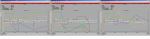
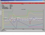
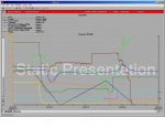
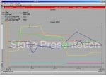
I have a generator that has an intermittent fault, which it looses load(kW) nearly instantly then go reverse load(kW), the PMS detects this issue then disconnects the generator from the bus. I have included trends from 3 generators that where paralleled at the time of fault. The fault is happening every couple of months. From what I can see is the generator 2 loses all load but only half its current. We can see the the exciter current increases on all 3 generators at time of fault.

Need to know where to look
1. AVR issue
2. Diode issue
3. Other issue
 

Attachments

@trentbliss,

Power = Vt * Ia * 3^0.5 * PF

where Vt is Generator Terminal Voltage (Volts)
Ia is Generator Stator Current (Amperes)
3^0.5 is the square root of 3 (presuming the generators are three-phase generators)
PF is the power factor (a value between 0 and 1)

An AC generator typically runs at a relatively constant terminal voltage; AND most AVRs have a limit to adjust terminal voltage of plus-or-minus 5% of rated terminal voltage (that's a pretty small window of adjustment).

The value of the square root of 3 is a fixed number: 1.7321--it never changes, not with load or voltage or amperage, it's always a fixed (constant) value.

The power factor varies depending on the reactive load(s) of the vessel (inductive, or capacitive capacitive) the machines are supplying and how much of the total reactive load of the vessel each machine is carrying (changed by adjusting the generator terminal voltage). Under fairly normal operating conditions the power factor of a machine or machines synchronized together should be as close to 1.0 as possible--this means that all the energy being produced by the generator is being produced as efficiently as possible. While this isn't always achievable for AC power systems on a marine vessel (ship) unless there are some very large inductive loads (motors driving pumps or fans, for example) the power factor of the loads on the ship should probably be around 0.8 to 0.9 lagging (in the inductive "direction"), and it should only change with large changes in load--usually large inductive electric motors.

So, let's look at the total power equation again. The value of Vt doesn't normally change by very much--generators like to operate at a stable voltage that isn't jumping up and down--so the value of Vt is, for all intents and purposes, near constant under normal operating conditions. So changing the generator terminal voltage isn't going to have a large effect on the power (watts, kW, MW) being produced by the generator. (Again, remember, the value of generator terminal voltage is usually limited to about plus-or-minus 5% of rated terminal voltage.)

The square root of three is ALWAYS fixed (constant); it doesn't change. Ever.

The value of the power factor can change depending on the electrical load(s) of the vessel, and you haven't told us if any large electrical loads are being started, running, or stopped when this condition occurs. BUT, a properly designed system (including the PMS) will make adjustments to try to compensate for starting, running and stopping of large electrical loads (using the generator AVR).

So, this leaves only ONE variable that has the most affect on the power being produced by a generator: Stator amperes. Generators are devices for converting torque (supplied by the generator's prime mover--a diesel generator, or a steam turbine, for example) into amperes. Those amperes can then be transmitted using wire(s) to areas around the vessel (or geographic area on land) to electric motors and computers and computer monitors and teakettles (or coffee machines) and televisions and lights which convert those amperes back into torque--either actual, real torque or "virtual torque" (which is my personal term for things that computers and televisions and lights do). Electric motors do most of the real work of electric power systems (driving fans, conveyor belts, refrigerators, pumps (fresh water; grey water; black water), air conditioners (a fast-growing segment of electrical consumption), etc. But lighting and heating water (for tea or coffee or sanitary use) is also important and requires energy which can be supplied by an electric power system comprised of generators.

One can't really have electric power without amperes. You can have full rated generator terminal voltage, and the square root of three, and a power factor of 1.0 or very nearly 1.0--but without generator stator amperes there isn't going to be any electric power. And one can't have zero power with some current flowing in the generator stator windings.

Without knowing what is happening when this condition you are facing occurs it's not very easy to say what might be the problem. Without knowing a LOT more about the PMS and how it works it's also difficult to say what part, if any, it's playing in this occurrence. But, to my mind, if the power output of a generator drops precipitously to near zero BUT the generator stator amperes don't ALSO drop to near zero, BOTH while the generator terminal voltage is remaining at or very near rated then there is something amiss with the load and/or current transducer(s) being used to provide load information to the PMS which is automatically disconnecting the affected generator from the electrical system of the vessel.

**CAUTION** DO NOT disconnect the current sensing wiring from the load transducer WITHOUT either shorting the current transformer terminals (where the current signal is produced/comes from) or without completely isolating the affected generator from the electrical system--including the load side of the generator breaker. Usually, the current signal is a very low voltage signal (mostly just amperes, a fraction of the actual amperes flowing through the generator stator) but when that current sensing circuit is disturbed (opened) while there is voltage and current flowing in the current sensing wires to the transducer the voltage in the circuit will float up to the voltage of the high voltage conductors in the center of the current transformer--440 or 480 VAC, or 6 kV, or 11 kV, whatever the generator nameplate voltage is. And that can be very dangerous for whomever is handling those current sensing wires.

To sum up, it seems the data you have been looking at is suspect. Highly suspect, based on the information provided. And, the "heart" of that data is the value of generator stator amperes the electrical system (including the PMS) is monitoring. Now, it may be that each phase of each generator ALSO has separate generator stator current sensing transducers feeding the PMS and other metering. The graphs you show--presuming the generators are three-phase generators--is only coming from one of the three phases of the generator. But, it certainly appears there is something amiss with the data because, first of all, it's very difficult to not have any electric power if there is current flowing in the generator stator windings. And, there can't be any power if there's no amperes flowing in the generator stator windings. Something doesn't seem right.

It could also be that one of the affected generator's stator windings has an intermittent problem. OR, that something is wrong with one of the conductors of the generator phases that is supplying load. Could be a lot of things, actually. Sometimes, especially with intermittent problems, troubleshooting is a logical process of elimination. You have to list all of the possible causes, and then prioritize them with the most likely causes at the top of the list, and then working from the top of the list down to either identify the problem or eliminate it from possibility. It takes some good planning and knowledge of the equipment and accessories, but it has to be done. Trying the "shotgun" approach might solve the problem, but it's difficult to know which one of the things that were done simultaneously actually solved the problem. (The shotgun approach to troubleshooting is popular with people who want to limit time spent troubleshooting (and limit loss of production) and just want to fix the problem as quickly as possible. It's usually not very effective, and because one doesn't know which one of the several things which were investigated and possibly corrected it's near impossible to know what the root cause of the problem was. THAT leads to LOTS of speculation, and usually false analysis of the problem.)

Please let us know what you discover and how you rectify the problem!
 
Maybe it's just my old eyes, but I find it very difficult to distinguish between the various colors of the data lines--for example, the "light" and "dark" blue lines for Generator Speed and Frequency. It would appear that something happened to change the engine speed and frequency but without knowing what the scaling of each of the signals is(are) on the graphs it's impossible to say how much they changed and which is which "blue line" on the graphs.

The other thing we don't know is the speed of recording: once-per-second, twice per second, ??? It looks like the data might be coming from multiple sources at different rates.?.?.?

Graphs are cool but can be very misleading. Without knowing scaling (vertical axis) for all of the signals it's difficult to analyze graphs, and because the data may be coming from multiple sources at different rates it's also difficult to interpret the data from the photos. We don't know if the data was from Phase 1, Phase 2 or Phase 3 (again, I'm presuming the generators have three phases).

But, still some recommendations have been made. Hopefully we will hear back from the original poster on the progress in resolving the issue(s).
 
Top