Facebook
 Google
 GitHub
 Linkedin
A Look Into CAM (Computer-Aided Manufacturing)
This article introduces the concept of Computer-Aided Manufacturing (CAM) and discusses some common uses for CAM for controls and automation specialists.
Computer-Aided Manufacturing, often referred to simply as CAM, has had a significant impact on several industries. A design can go from an idea in an engineer's mind to an actual part ready for use in a more seamless, often faster manner by leveraging the power of computers and technology that has a solid foundation in controls and automation.
What is CAM (Computer-Aided Manufacturing)?
According to Autodesk, one of the leaders in CAM software, Computer-Aided Manufacturing is "the use of software and computer-controlled machinery to automate a manufacturing process."
The process of creating a part using CAM begins with the creation of a 3D solid model. From that solid model, toolpaths are generated (think of the path that the nozzle on a 3D extrusion printer follows when generating a part).
Those toolpaths are converted into a language that the CAM machinery can understand. In CNC machines, that language is M and G codes that provide key information such as position, cutting speed, and depth of code. Once the instructions are in place to generate the part, they are sent to the CAM machinery.
Software
Software is a key part of any CAM system and includes the software used to create the solid model, generate the toolpaths, create the instructions for carrying out the toolpaths, and interfacing with the CAM machinery.
Different software packages specialize in various things. One application may make it easy to create excellent solid models and evaluate them for suitability before manufacturing. Another package may have special algorithms that can take an STL (stereolithography) file of the solid model and generate the most efficient toolpaths and instructions for creating it.

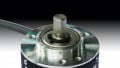
Solid models such as this are critical to the CAM process. Image courtesy SOLIDWORKS.
In some instances, 3D scanning and measurement may start developing a part rather than starting a solid model from scratch. It is also important not to forget the programs and code that power the controls necessary to implement those toolpaths with accuracy and precision.
Toolpaths
Toolpaths are key to CAM, and the term finds its roots in CNC mills and lathes. For a milling machine, those toolpaths usually indicate how to move the blank relative to the cutting. When using a laser cutting system, the toolpaths tell the system how to move the laser relative to the part.

Many different toolpaths can achieve the same effect, but some will be faster and more efficient than others. Image courtesy Open Mind.
To generate additively manufactured parts, the toolpaths indicate how to move the printing head is to move relative to the base where the part is being built. In laser sintering, tool paths control how the deposition head moves.
Machinery
There are many different types of technology used in computer-aided manufacturing. This includes more traditional CNC (Computer Numerical Control) milling machines, lathes, and grinding machines that automate the material removal process, as well as newer approaches such as robotic sanding tools.
Some cutters use lasers, plasma, and even water, all of which require a fraction of the time needed to accomplish the same processes by hand. For example, EDM (Electrical Discharge Machines) can cut through nearly anything using the heat from a powerful electrical spark.
Additive manufacturing is another key area of CAM. In 3D printing, a part is built up layer by layer with a minimal amount of material wasted. This is in contrast to cutting processes that remove unwanted material and leave behind the final part.
There are various additive manufacturing processes, including material extrusion, FDM (fused deposition modeling), vat polymerization, powder bed fusion, and SLA (Stereolithography). Keep in mind that additive manufacturing is not limited to polymers but includes metal as well.
What Role Does CAM Have in Manufacturing?
The role of CAM in manufacturing is increasing in importance, which ties in heavily with its benefits. One of these is that CAM allows the design process and manufacturing process to be better integrated, allowing for a seamless transition from the initial idea to the final part. In the solid modeling phase of design, parts can be virtually checked for fit and interaction and detailed FEA analysis and simulation.
Those same models can then be used to create prototypes, then modified when design changes are necessary. Again, those models are used to generate the final component.
One of the outstanding aspects of CAM is the high level of precision and repeatability that is possible, which can be critical for parts that demand high tolerances, both in terms of dimensions and shape. It is ideal for creating complex geometries such as aerospace applications, including blisks and turbine blades.

Complex turbine surfaces can be generated in software and made a reality using CAM. Image courtesy of Autodesk.
CAM machinery can be reconfigured to make other parts, reducing downtime between production runs. This also means that one machine can be used for a wide array of projects, which can be ideal for smaller businesses operating on limited budgets.
CAM projects can also be sent out to companies that specialize in CNC or additive manufacturing. That means that even if a facility does not have the equipment they need to produce the quality components that are necessary, they can still take advantage of the precision and accuracy of CAM.
Because CAM includes basic STL files that can be shared and adapted for use in different machines, it has proven key in manufacturing certain parts when there is a shortage. An excellent example of that involved the 3D printing of diffusers for medical inhalers intended for COVID-19 patients: the STL files for the diffusers were made available on a website so that more hospitals could have their own made.
It is also evident that CAM automates manufacturing on the factory floor, where it can speed up the product development process and its manufacturing and deployment on the market.
Common Uses of CAM
CAM parts and components are often found from the earth to the sky. Parts for a mini-USO cosmic UV telescope on the International Space Station were manufactured by Stratasys using their 450mc FDM 3D Printer.
In the aerospace industry, 5-axis CNC machining has become commonplace for manufacturing blisks (integral bladed disks). It is even finding applications in architecture where people can use it to cut cladding and 3D printed homes (such as those printed by SQ4D).
However, CAM is not just for complicated systems. CNC milling machines make extremely fast yet accurate work of drilling holes and cutting simple surfaces. Automated tool changes mean that the engineer can carry out multiple actions without the part leaving the machine. CAM technology can even be used to lay and shape composite parts such as automobile bodies or kayaks.

Additive manufacturing is used in medicine, such as this example of a customed brace that still provides the necessary stiffness but at a reduced weight. Image courtesy of Formlabs.
CAM is a powerful tool for manufacturing, from the rapid yet precise drilling of the numerous openings in engine blocks to the often slow but highly controlled additively manufacturing metal turbine blades. It provides a host of benefits to its adopters, and every year the technology that supports it is increasing in capabilities.
Even if a machine for basic 3D printing is only used to generate prototypes, it can speed up the time between design and market.
Without the continued evolution and advance of controls and related technology, there would be no CAM.