Facebook
 Google
 GitHub
 Linkedin
An Overview of Visual Servoing for Robot Manipulators
Robot Manipulators, also known as Robot Arms, are found just about everywhere nowadays seeing as their versatility puts them at the forefront of manufacturing innovation. In this article, learn about Visual Servoing and how it's used for industrial and commercial applications.
Robot manipulators (often known as robot arms) are extensively deployed in manufacturing, packaging, and processing factories. Traditionally, manipulators were programmed once and deployed to work incessantly on automobile assembly and object pick-and-place applications. Modern factories and industries have introduced robotics applications to tasks with human collaboration as well as autonomous intelligent task execution in unstructured environments.
Application of manipulators in autonomous operations for bin picking, welding, torquing, painting, deburring, inspection, and other tasks primarily utilizes the visual servoing, perception, and motion planning concepts from robotics. This article gives a technical overview of visual servoing applied to manipulators for industrial and commercial applications.
What is Visual Servoing?
Visual servoing is the method of controlling a robot’s motion using real-time feedback from vision sensors to execute tasks. Computer vision methods extract features from the robot’s operational scene and determine how the robot should move in order to articulate the image features or converge to the task workpiece. The techniques are heavily reliant on good camera calibration, an accurate kinematic model of the robot, good IK and FK solvers, and satisfactory camera performance (good pixel resolution, FPS, shutter speed, etc.).
Visual servoing is analogous to a PID controller, a model-free approach to actuate the robot based on the reference high-level task to be executed. The image information is transformed into useful task progress metrics. The robot is instructed to move in order to align its current task progress metrics with the desired task metrics and gradually reduce the error between the two.

Figure 1. Visual servoing process flow
Mathematically speaking, visual servoing attempts to minimize the error e(t) defined by:
e(t) =f(m(t), a) - f*)
where m(t) is the collection of regions of interest in the image and a is the collection of camera intrinsic and extrinsic parameters. The function f* represents the desired set of visual features while f(m(t), a) represents the actual visual features (such as object pose or coordinates of an object/feature in an image).
A real-world 3D object/scene is projected onto a 2D image in monocular cameras while depth cameras include the third dimension as well and help execute more sophisticated tasks. Depending on the positioning of the camera, visual servoing has two paradigms: eye-in-hand and eye-to-hand (see Figure 2).

Figure 2. Camera-mounting-based visual servoing paradigms
The camera is mounted on the end-effector of the robot in the eye-in-hand configuration while it is mounted on a fixed location in the world. Thus all camera observations made in the eye-in-hand paradigm are with respect to the camera which has a known transformation with respect to the end-effector of the robot ( which is in motion). Meanwhile, the eye-to-hand paradigm has fixed a camera frame with known transformation from the robot base or another origin.
Commonly Observed Visual Features & Detection Methods
Several image processing and computer vision methods are applied to extract meaningful information from a scene or consecutive images (using optical flow) and conform them to servoing scheme dimensions. These features could either be high-level scene information like object detection, object recognition, and semantic segmentation or minute pixel-level information like edges, lines, facial features, corners, color blobs, and ridges.
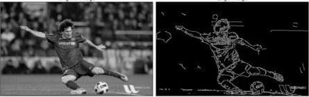
Figure 3. Canny Edge Detector available in OpenCV. Image courtesy of OpenCV.
Feature extraction tools like Canny detector, FAST corner detector, Shi-Thomas corner detector, and algorithms like SIFT, SURF, BRIEF, and ORB have been used in classical image processing applications. New deep learning techniques have also been deployed lately for enhanced image interpretation and more dynamic object-level (object pose, orientation, dimensions, type, etc.) information extraction.
Common Visual Servoing Schemes
Visual servoing has two main schemes on the basis of camera mounting:position-based visual servoing (PBVS) and Image-based visual servoing (IBVS). These schemes are differentiated on the basis of the function defined for the error formulation. PBVS transforms visual information into real-world 3D pose information while IBVS looks for visual features and their convergence in the image dimension itself.
Position/Pose-based Visual Servoing
PBVS usually uses depth cameras to obtain the 3D pose — position (x, y, z) and orientation (Euler or Quaternion) — of the regions/objects of interest and compares the robot’s end-effector’s pose against it. The error term e thus formulated is the Cartesian pose difference between the two and the servoing scheme attempts to minimize it by moving the robot around, ideally towards the final desired pose. For example, based on the location of the object to be grasped seen in the image, the scheme generates the ideal grasp pose (which may keep changing due to relative change in camera pose) for the end-effector and tries to converge the robot to it.

Figure 4. PBVS workflow
Since PBVS works with real-world poses, it needs at least a 6-DOF robot arm to successfully implement the solution without getting stuck in local minima. It also uses robot inverse kinematics to convert Cartesian control instructions into joint angle values for the robot. Since obtaining the 3D pose involves the conversion of information from the camera frame to the robot frame, camera calibration plays a significant role in the process.

Figure 5. Position-based visual servoing
Image-Based Visual Servoing
Unlike PBVS operating in the real-world 3D pose, IBVS extracts camera features and then formulates the error in the image plane itself. On an intuitive level, if the position coordinates of the desired feature in an image are [0.2, 0.5] and the current position coordinates of the image are [0.5, 0.5], the visual servoing scheme tries to converge the feature to the desired coordinates and moves the robot accordingly.

Figure 6. IBVS workflow
The first step of IBVS is the projection of the 3D image on a 2D image plane. The image feature extraction in IBVS is prone to poor camera performance, synchronization issues, and computational requirements. Owing to the mathematics, to define the control logic for a 6-DOF robot arm, at least three features are needed in the image. The feature Jacobian (which encodes the information about the motion of image pixels) is responsible to derive the control signal for the robot by relating the motion in feature pixels against the same for the end-effector.

Figure 7. Image-based visual servoing scheme
Mathematical Aspects of Visual Servoing
For the error function
the control law for the robot is proposed as:
which derives the velocity vector q for the robot. This velocity vector could either be Cartesian or joint space velocity.
The pseudo-inverse of the Jacobian matrix or the interaction matrix J is:
The Jacobian represents the motion of the image pixels or features.
Projection of a 3D image on a 2D image plane is one of the most intricate steps of visual servoing. A world point (X, Y, Z) projects in the image plant to (x, y) such that
and
where (u,v) are the pixel coordinates of an image point and the camera parameters are . Coordinates of the principal focal point,
is the focal length and is the ratio of pixel dimensions.
Further mathematical derivations are beyond the scope of this article but the attempt is to acknowledge how the different aspects are put together to use the visual servoing algorithm.
Industry Applications of Visual Servoing
Since an industrial setting involves multiple dynamic elements, ambient lighting issues, and system inaccuracies, visual servoing technology capable of such scenarios is still a work in progress. However, a lot of industries do use visual servoing for bin picking, packaging, and sorting tasks in a controlled environment.
Applications involving a moving workpiece or a moving robot, like conveyor belt sorting, welding using a mobile manipulator, human-robot object handover, and similar collaborations are all examples of visual servoing. A situation ideal for visual servoing where a human would not be preferred is garbage sorting. Several exploration rescue tasks for mobile manipulators use visual servoing to avoid localization inaccuracies. Also, in a limited capacity, visual servoing is being explored for surgical robotics applications like automated or assistive surgeries.
A Review of Visual Servoing
As computer vision and AI research continues to make forward strides, a lot of autonomous robot operation is proposed to address the lack of labor in these industries and visual servoing is one the most important technologies for this issue. Industries often need robots to be running at lightning-fast speeds. While visual servoing is promising, it is far from achieving speedy performances.
The computational bottlenecks in image processing and inverse kinematics are being worked on with the hope of addressing them using GPUs and parallel programming. The next article in this series is a walkthrough of the automated bin picking pipeline used in industries that involves several intelligent robotics techniques as well as few conventional robust industrial elements.