Facebook
 Google
 GitHub
 Linkedin
CNC Software vs. PLC Software
It can be easy to group CNCs and PLCs together since they are both run by digital processors and programs. Are they interchangeable? This article explores the possibility on a software level.
Two major categories of digital control systems can be seen throughout different areas of industry: CNC machines creating parts and products at a component level, and PLCs which dictate the actions of entire systems. Sometimes it’s easy to group these machines together since they are both run by digital processors and programs. However, since they perform two different tasks, it’s important to note the differences between the two systems.

Figure 1. A technician programs a CNC controller.
If you ask a programmer whether a PLC can be used in place of a CNC controller, the answer might be a frustrating variation of “Well, yes and no.” On a surface level, they are both run by programs and they can both interface with inputs and outputs. So it might be fair to say that, in theory, you could program a PLC to run virtually any manufacturing machine, regardless of size and number of axes.
However, a more logical answer to the question might be “A PLC could perform some of the most basic tasks of a CNC machine, but would be impractical for most modern machines.” The reason for such an answer would come from a look into the software driving each of the machines. Then the differences are seen more clearly.
The Needs of a CNC Program
In order to assess how well a PLC might work in a machine environment, it would be useful to investigate how a CNC controller receives instructions and what those instructions look like.
The acronym CNC stands for Computer Numeric Control. The actual controller module (which might be an actual PC or laptop) translates lines of readable text into actions for the motors and tool heads. For small machines, the controller will usually have a port to connect a computer to download the program (USB or RS-232 for example) as well as a number of connection terminals for the motors and limit switches to provide homing abilities. Some controllers may also use encoders to obtain precise positional data.
The lines of readable text begin with G and M prefixes commanding either geometry or machine data. Geometry data tells the machine where to go, and machine data adjusts speeds and settings to obtain just the right actions according to various materials and tool paths. For this reason, these codes are often called G-codes or M-codes.
The code for a complicated machine part may consist of thousands of lines of code with each G-prefix line incrementing the tool head another thousandth of an inch, possibly in multiple axes simultaneously. The entire code could be viewed as a giant array of one motion command after another. Each tiny incremental step is required to finish a single larger task.
The lines of G-code may sometimes be entered manually, but this is difficult and only recommended for advanced users. More commonly, a 3D digital component will be opened in computer-aided machining (CAM) software such as FeatureCAM, MasterCAM, or one of many others. After the settings for the CNC machine are correctly entered, the whole code is automatically generated. Again, this may be thousands of lines long. With an experienced eye, some manual modification may create a superior part, but it would take a very long time to make the entire code from scratch.
The Purpose of PLC Codes
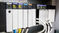
The ladder logic that drives a PLC is based on an entirely different theory of operation. A PLC scans each line of the program as quickly as possible over and over, updating output terminals and communicating with external equipment as required according to the logic combinations of the inputs.
Ladder logic does not work on a step-by-step approach to system function — it is actually quite difficult to accomplish this task. A PLC is designed to monitor physical input devices and send commands to physical output devices.
The problem with relating this environment to a CNC machine is that until a part exists, it is not physical. In other words, until you have actually finished machining the component, there would be nothing for the PLC inputs to monitor. Therefore, the entire PLC code would need to operate without any interaction with the physical world. This is not how PLCs were designed to work.
There is a type of programming in PLCs which is called sequential function chart (SFC) programming. This gets a bit closer to the idea of a CNC machine, but it is still designed for the use of physical triggers to transition from one step to the next. In a CNC system, there are no triggers. Only the completion of the previous step is required to move to the next.
In one sense, a small PLC may aid a CNC controller. If a spindle is run with a VFD, it can often be quite advantageous to run that drive unit with a PLC. Sometimes even this is unnecessary since many CNC controllers output 0-10 volt analog signals to adjust a spindle RPM.
Generating the Code
The final challenge of using a PLC in place of a CNC controller is the origin of the code. CAM software outputs G and M commands, and there isn’t an equivalent in a PLC software suite. Unless a translator software exists, it can be very difficult to generate the required complex code to create the component.
Conclusion
It is not impossible to use a PLC in place of a CNC controller. However, it comes with many challenges that can make it overwhelmingly difficult. Most likely, if a machine had a CNC controller before, it might be most logical to replace it with another CNC controller designed for the job. So, can you use a PLC in place of a CNC controller? The final answer is still “well, yes and no.”