Facebook
 Google
 GitHub
 Linkedin
Force Control | An Adaptive Method of Robotic Navigation
Learn about force control in robots and what sets it apart from typical point-to-point programming. This feedback method can overcome many small irregularities in manufacturing processes.
Traditional robot programming involves a method called 'teaching.' This involves moving the robot to a position, either by jogging or by manual handling, then saving that point to memory. Repeat this process a dozen or so times, and the robot can progress through each of those points in a perfectly repeatable cycle. For these robots, consistency is key. If the process doesn't change, this programming method is wonderful.
But what if the workpiece isn't exactly the same every time? What if there are surface irregularities or multiple part revisions with very slight differences?
What is Force Control?
Force control is a method of monitoring and adapting to forces that a robot experiences during movement. These forces can come from the robot itself (speed, inertia, tool payload), but they can also come from outside the robot, from its environment.
Monitoring these forces produces vital information for use in the manufacturing process.
There are two systems for monitoring forces on the robot:
Internal Torque Sensing
Internal sensing is built into all robot systems. All industrial articulated robots, especially those designed for collaborative applications, include some element of current sensing for the motors and torque sensing for the joints. The internal force control system is regulated inside the robot cabinet itself and implements a controlled or emergency stop if the sensed torque exceeds a certain threshold. This system is all required according to safety standards.
External Torque Sensing
Third-party external systems require mounting some type of force/torque sensor on the end of the arm with feedback wires to the control cabinet. These sensors detect forces in 3 linear axes, and, usually, torque in one or more rotational axes.
The sensor works by monitoring the force vector in the desired direction and sends a feedback signal to the robot. This information is used to adjust the servo motors to any environmental changes. These developments can be displayed and graphed over time for a better understanding of what the arm is experiencing during each cycle.
Using this information, a programmer can examine drops or spikes in torque in order to better program the robot for specific scenarios. The use of this function can often lead to the elimination of a significant number of sensors and complexity in the robotic cell.
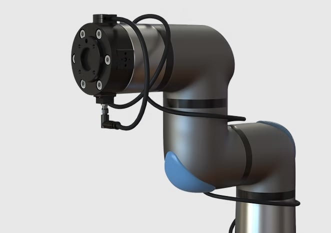
Figure 1. A force-torque sensor attached to the end of a robotic arm. Image used courtesy of Bota Systems
Force sensing can be a huge advantage, but to understand the applications, it's helpful to think about the decision-making process that happens inside the controller. When a certain force is sensed, the robot doesn't simply stop or set an alarm flag. Instead, it can be programmed to slightly adjust or move to another destination point when the force is sensed. In this way, we can say it's a force-controlled program, rather than the traditional point-to-point program.
Common Applications of Force Control
Grinding
Force control is often very useful in robotic grinding or deburring applications following a machining process. When using standard programming methods, the robot moves through points in space at a preprogrammed velocity regardless of changing forces on the arm. This can cause problems in situations where some weld slag or surface roughness might cause a collision. Instead, thinking about the situation more like a human operator, a constant force will be applied with the grinder until the surface is completely smooth, no matter what it looked like at the beginning.
It is also an advantage when the grinding tools begin to wear. For example, when a sanding belt has recently been replaced, it will grind material away from the part much faster than one that is nearing the end of its lifecycle. The difference in the force experienced on the part at a given feed velocity can be significant. Using force control, the robot can adjust the speed or position of the part being abraded to create the desired finish, while also reducing wear and tear on the tooling.
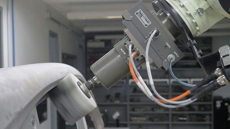
Figure 2. This force sensor is directly between the motorized tool and the end of the robot arm. Image used courtesy of ASIS
Part Differentiation
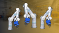
Torque feedback can also be helpful in a process where parts of different lengths, sizes, or positions are being handled. In this case, the robot searches in a known direction to find the location of the part, creating a pick point that must then be retained in order to relay position data to other collaborative robots in the system.
One example of this is a part-picking cell with multiple robots. Parts arrive in a feed chute in a random position. The first robot moves its gripping tool toward the general part location until the force sensor detects that it has touched the part. The robot continues pushing the part gently until the part comes up against the edge of the chute, as detected by the force sensor. This can repeat in multiple directions. The robot now knows the exact position of the part, and can effectively hand it off to other robots in the system.
This solution will work for parts of multiple sizes and shapes. The only alternative is a powered angled conveyor or a mechanical fixture that moves the part automatically, a fairly rigid and unflexible process.
Precision Part Fit-Up
Part fit-up, or insertion of precision parts, often leads to binding if the parts aren’t aligned exactly. With force feedback, a robot can adjust alignment when inserting tight-fitting parts into one another. Instead of following a preprogrammed path, a robot can essentially “feel” when the parts start to bind and change paths accordingly. A torque spike signals when the part bottoms out in the fit-up, notifying the robot that the part is in its final position, and it is now clear to move to the next task.
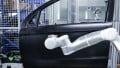
A specific method of part insertion is twisting or rotating two parts, to lock them together. This method requires a robot to grab a part from a pick point and press the part against a receiving half. It then rotates and pushes the part until it achieves the correct orientation and the two parts join and lock together. An example of this type of fit-up is robotically placing a wheel on a car. A robot picks the wheel and moves to center it on the bolt pattern until the wheel slightly presses against the lug nuts. The robot then turns the wheel on its axis until it slides onto the studs, creating a sudden decrease in torque on the robot. After the drop in torque, the robot stops spinning the wheel. It can then push the wheel onto the studs until it sees another torque spike, letting the robot know it had pushed the rim all the way onto the car.
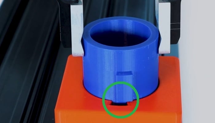
Figure 3. Part fit and insertion control can compensate for small positional errors. Image used courtesy of ROBOTIQ
Implementing Force Control
The various applications described are only a few of the ways force control can be used to reduce the number of sensors necessary on a cell. When implementing force monitoring on any robotic system, be sure to follow the manufacturer's recommendations before attempting to program the system in an unconventional manner.
Keep in mind that some robots may not be available with internal force control and will require a retrofit using an external system. On the other hand, robots outfitted with an internal feedback system are often priced higher, as force control is considered an extra accessory in the robot package.
Be sure that the additional cost will be offset by the versatility created in the robot. Sometimes a simple sensor will do the job as effectively for a much lower cost.
However, eliminating a large number of sensors by implementing force control often saves the customer money by reducing the number of sensors needed and possibly cycle time.
Original article published Feb 2020