Facebook
 Google
 GitHub
 Linkedin
Comparing Parallel Circuits: Practical vs Theoretical Electrical Systems
We are taught that parallel circuits maintain equal voltage across all branch resistors, equally sharing the source voltage. But reality is often far from ideal, and individual devices certainly impact the rest of the circuit.
We have a saying around here. It goes “yeah, that should work, in theory.”
Series and parallel circuits are well understood (at least on paper) by most engineers. Somewhere back in some physics, introduction to engineering, or circuit analysis class, every engineer has learned that components in series have the same current running through them and components in parallel have the same voltage across their terminals.

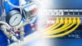
Figure 1. In theory…
On paper, this works out great. An engineer can design a system with hundreds of components suspended between a power rail and a ground rail, knowing that their voltage drop will be the same. However, during installation or during intended use, seemingly random problems appear. What happened?
Voltage Drop of the Wire in a Practical Circuit
In circuit diagrams, it is assumed that the resistance in wire is zero, meaning there is no voltage drop from one end of the wire to another, regardless of its length. In many cases, this is a fair assumption because the voltage drop of the wire is negligible compared to the other circuit components. However, this assumption begins to fall apart when many wires or long wires are used, such that the wire’s resistance becomes significant.
Furthermore, for alternating current (AC) and other time-variable signals, the wire’s impedance, meaning its frequency-dependent resistive characteristics, will also change. Current passing through a wire will generate a magnetic field, and current flowing in adjacent conductors generates an electric field. These represent inductive and capacitive loads that contribute to the impedance calculation.
Power Source Limitations
Back in circuit analysis class, not only were wires assumed to be ideal, but power supplies were as well. A constant voltage supply was expected to deliver the same voltage at all times, and AC supplies only produce perfectly pure sine waves at a given frequency and amplitude.
Anyone who has had a dead battery or a brownout has experienced a time where the power supply did not live up to this assumption. In either case, devices needed a certain amount of power (either specified in Watts or in a voltage and current requirement). Enough of them were connected that the battery or power plant simply could not deliver that much power.
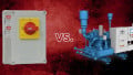
If the power consumed by a particular load happens to be higher than most others (perhaps one large CNC machine or a motor in a facility that otherwise only runs small equipment), that device will cause the most significant change in the source voltage. When this large machine is de-energized, the voltage of the other branches will be higher. The moment the large machine turns on, accelerates, or otherwise changes, the voltage of all the branches may be affected, even though they should all hold steady at the level of the voltage source… “In theory”.

Figure 2. Large loads, especially inductive loads, consume lots of power when starting up and running. Image used courtesy of Canva
More Branches Added to a Parallel Circuit
By adding more and more branches to a parallel circuit, the power requirements increase, even though the voltage across each branch theoretically remains constant. A common problem in industry is expanding an existing control system by adding components as a new parallel branch. For the most part, this works and is convenient, as there is probably already a power rail and a ground rail in place. This cannot work forever, and at some point the total power requirement exceeds the available power as supplied.
This can be a frustrating problem, as it can be the new components that look faulty, in which case, they get sent back to the manufacturer, only to have the replacements not work either. In other cases, an older component will look faulty (but simply may not receive enough power). Furthermore, these can occur during intermittent loading, as relays close, pumps or motors start, and so on, adding to the troubleshooting nightmares.
Another problem is that, even if the power supply can support the increased load, the main wires leading from the power supply will see increased current. From Kirchoff’s Current Laws, the currents must add up. A common problem that arises is new components blow the fuse or trip the breaker on the main leads from the power supply due to the increased current.

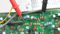
Figure 3. Each branch circuit is unique, with different lengths of wire and nearby equipment which can affect other branches. Image used courtesy of Canva
A Quick Example
The author of this article runs multiple pieces of amateur radio equipment in his car. Everything in the car is powered by the car’s battery, which is being charged by the alternator when the car is running. At steady state, the car is likely powering the car electronics (0.1 A @ 13.8 V = 1.38 W), a smartphone charger in the cigarette lighter (~ 5 W), an inverter for converting DC to AC for certain devices (300 W), a Very High Frequency (VHF) radio (1 A @ 13.8 V = 13.8 W while receiving), and a High Frequency (HF) radio (1 A @ 13.8 V = 13.8 W while receiving). Periodically, the author will transmit on either the VHF or the HF radio (50 W or 100 W, respectively). Most of these devices are connected through a distribution panel, connecting them (roughly) in parallel with the car’s battery and the alternator.
One day, he found that the car stereo would reset when he transmitted on the VHF radio. The stereo display would flash and sometimes it would auto-eject the CD that was in it. At first glance, this looked like a radio-frequency interference (RFI) problem as it was tied to the act of transmitting.
After a few more days, the smartphone charger would stop charging momentarily during transmitting, and the smartphone may or may not recognize the charger when the power was restored. More RFI problems?
About a week later, the car had a dead battery. As it turns out, the alternator was dying, and needed to be replaced. The weak alternator could not deliver the required power to run all of the devices (a problem the author has in all of his radio-laden vehicles).
What is particularly interesting about this situation is that the 300 W inverter never noticeably hiccuped during this process, even though it consumes the most power. Just because a device uses the most power does not mean it will be the first affected by a power drop. In this case, capacitors acting as a short-term power reserve provided necessary power for these short drops, but only to the inverter.
Voltage Drop in Parallel Branch Circuits
As the saying goes, “in theory, there is no difference between theory and practice, but in practice, there is.” So it is with actual circuit components versus idealized components and circuits drawn on paper or in a circuit CAD program.
Often, these nuances will appear in frustrating ways: a controller randomly restarting or fanout flipping a bit in a digital circuit. When troubleshooting these intermittent problems, consider that one cause could be too many parallel branches on a single power source. This will not always be the case, but it is simply another potential problem to check.
As is always the case in troubleshooting, quick documentation can lead to better analysis.
Noting when problems first occurred, while also having access to when certain machines were installed or serviced, will point a good technician to the exact source of the problem before major machine failure can occur.
At least, in theory.