Driving DC Motors: Rectifiers vs. Pulse-Width Modulation
Although DC motor technology has a strong legacy, control strategies vary from simple to complex. Designs must consider not just the motor, but also the electrical supply and the environment.
A DC motor drive is a device that regulates the operation of a DC brushed motor by controlling its speed or direction. It is the interface between the motor and the power supply, manipulating the electrical input to achieve desired motor behavior. The drivers for brushless (BLDC) and stepper motors are entirely different, so the topic of discussion today is brushed DC motors.
DC motor drives come in various types, with the two primary categories being silicon-controlled rectifier (SCR) and pulse width modulation (PWM) drives.
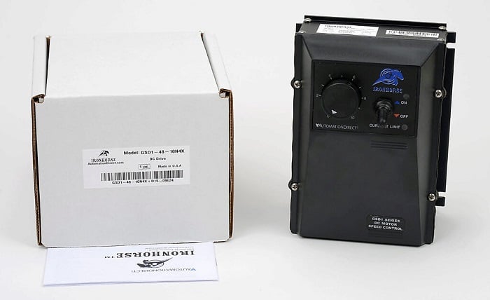
Figure 1. A DC motor drive with a PWM output and a NEMA-enclosed frame. Image used courtesy of Automation Direct
SCR and PWM Outputs
An SCR is a solid-state device with three parts: an anode, a cathode, and a gate. It works like a diode, letting electricity flow in one direction (from anode to cathode), but only when a trigger voltage is applied to its gate. Once triggered, it stays conducting even if the gate signal is removed until the positive voltage at the anode stops. When used to convert AC to DC, the SCR is turned on during the positive part of the cycle. Then, as the voltage reaches 0 at the end of the positive cycle, the SCR switches off.
The timing of the trigger signal determines the firing angle, which is the exact point in the sine wave at which the SCR turns on. When it's turned on, electricity goes to the motor winding. The firing angle also affects the average voltage and the output speed. If fired early, electricity goes to the windings for longer, and the average voltage is higher.
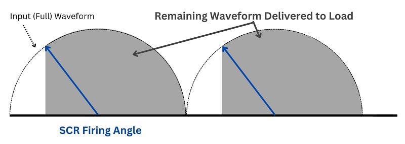
Figure 2. This image clarifies the "firing angle" concept in SCR controls. Image used courtesy of the author
In PWM circuits, a transistor or SCR is used to control voltage. When the transistor turns on, electricity flows through the motor. The timing of when the transistor/SCR starts and stops conducting (called the duty cycle) decides how much average voltage goes to the motor and how fast it moves. If we widen the pulse, more voltage goes to the motor on average, making it move faster.
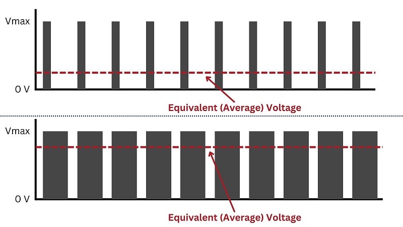
Figure 3. This image clarifies a PWM control circuit and how the pulse width determines the average voltage. Image used courtesy of the author
Four Common Speed Controls for DC motors
Unfiltered Half-Wave SCR Control
The unfiltered half-wave SCR method is the simplest speed control method with the fewest required external devices. The half-wave method involves connecting a single SCR in series with the motor's armature winding. Since the SCR is a diode, it removes the negative portion of the wave, and the motor will only rotate in one direction. While simple, this creates an uneven current supply since the AC wave rises from 0 volts, to full (line) voltage, then back to 0 volts, then remaining at 0 volts while the negative half of the wave passes.
Unfiltered Full-Wave SCR Control
The full-wave (also called bridge) SCR control enhances the half-wave SCR control by using two SCRs and two diodes to not only pass the positive half of the AC wave, but also to reverse the negative half into a positive voltage. This output moves closer to resembling a DC wave, but it still rises and falls from 0 volts to full line voltage, so the current is far from steady. With a 60 Hz line frequency, the motor will be quite resilient to these quick fluctuations, so this is sufficient for simple and low-cost motor drives.
Filtered Full-Wave SCR Control
The next step in complexity is to add a (usually large) filter capacitor across the rectifier’s output. By storing energy while the AC sine wave approaches full line voltage, it can gradually release it while low voltage is reached, effectively ‘smoothing’ out the choppy profile caused by the rise and fall of the AC wave. This bridge rectifier is common in nearly all power supplies, but for motor control, the SCR is an important distinction because it allows the motor to receive power only when directed by the controller.
Pulse Width Modulation (PWM)
A filtered pulse width modulation (PWM) control is the most complex of the methods. The voltage is first converted from AC to DC with a full-wave rectifier, then an SCR is fired on and off rapidly in series with the motor’s windings. The timing of the pulses is controlled by a processor that is external to the power circuit. By varying the ratio of on time vs. off time, adding to the relatively slow response time of the motor, the total output is equivalent to a variable, yet smooth, DC current.
Higher HP Drives use SCR Outputs; Why?
Due to several key factors, SCRs are favored in drives requiring higher horsepower (HP). First, they have impressive current and voltage ratings, handling tens to hundreds of amperes and several hundreds to thousands of volts. This capability suits them for high-power applications typical in larger motors or industrial machinery. SCRs also exhibit low forward voltage drop when conducting, resulting in minimal conduction losses. This efficiency is crucial in high-power setups, where reducing losses enhances overall efficiency.
In contrast to transistors, even popular field effect transistors (FETs), once triggered, an SCR remains in the ON state until the current drops below a certain threshold, ensuring reliable operation vital for systems where downtime is costly. The gate control mechanism allows for precise and rapid triggering with a small gate current, ideal for applications requiring accurate control. Combining high ratings, low losses, reliability, precise control, and fast switching, SCRs prove highly suitable for higher HP drives, emphasizing reliability, efficiency, and performance.
DC Motor Drive Frames: Open Vs. NEMA Enclosed
When deciding between open and NEMA-enclosed motor drive enclosures, factors tied to the application and operating surroundings determine your choice.
Open Frames
Choose open frames when your motor operates in a clean, dry setting with minimal exposure to contaminants, moisture, or harsh elements.
Benefits of open frames:
- Cost-effectiveness: Open frames are typically less expensive than NEMA enclosed frames due to their more straightforward build.
- Adequate ventilation: Open frames offer ample ventilation to maintain motor temperature in environments where cooling isn't a significant concern and contamination risk is low.
- Space considerations: Open frames' compact design makes them a favorable option if space is limited.
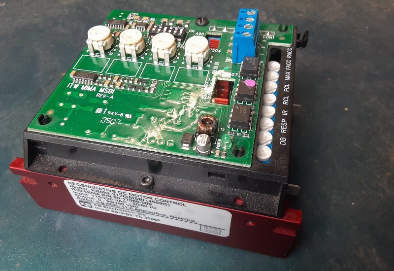
Figure 4. This DC motor controller has an open frame. Image used courtesy of the author
NEMA Enclosed Frames
Select NEMA-enclosed frames for applications where the motor faces moisture, contaminants, high humidity, or other harsh conditions that could compromise its performance and longevity.
Benefits of NEMA-enclosed frames:
- Enhanced protection: NEMA enclosed frames offer superior safeguarding against moisture, dust, and various environmental factors, ensuring prolonged motor lifespan and reliable operation.
- Safety compliance: NEMA enclosed frames are required in industries mandating enclosed motors for personnel and equipment protection.
- Versatility: NEMA enclosed frames are available in various types tailored to specific environmental challenges (e.g., TEFC, TENV, WPI, WPII). These frames provide flexibility to match the enclosure to application needs.
Reversing Vs. Non-Reversing DC Motor Drives
Reversible DC motor drives are widely utilized across various industrial sectors. They provide essential bidirectional motor operation for tasks like material handling, conveyor systems, robotics, and automotive assembly. Manufacturers offer a diverse range of these drives to meet the varied needs of such applications.
However, there are scenarios where a non-reversing DC drive may be preferable or necessary. When the motor operates solely in one direction, such as pumps or fans, a non-reversing drive simplifies the control system by eliminating the need for reversible functionality. Cost savings also drive the preference for non-reversing drives in applications where bidirectional operation isn't required.
Quick Summary: Differences in AC and DC inputs?
When a DC motor drive controller is used with an AC voltage input, it includes a rectifier circuit that changes the alternating current (AC) to direct current (DC), which DC motors need to function. This rectifier generally uses diodes or thyristors to flow the current in only one direction. On the other hand, if the input is DC voltage, the controller can use this directly to operate the motor. Sometimes, additional components may be needed to adjust or stabilize the DC voltage according to the motor's specific needs. This versatility allows the controller to be effectively used in various settings, whether there's access to AC or DC power.
Typical Input Voltages Available
Standard input voltages for DC motor controllers vary widely to accommodate different applications and setups. For AC inputs, typical voltages include 12 VAC, 24 VAC, 120 VAC, and 240 VAC, covering a range from small, low-power devices to more substantial machinery used in industrial environments. On the DC side, standard input voltages commonly range from 12 to 48 VDC. This variety ensures that options are available for everything from basic projects to complex automation systems.