Facebook
 Google
 GitHub
 Linkedin
Grounding and UL 508A Standards - Part 2, Sizing and Power Supplies
Additional rules for the grounding and bonding of industrial control panels include the sizing of ground conductors and the conditions that dictate when power supplies and transformers must be grounded.
Understanding grounding and bonding for industrial control systems is no simple task. In an earlier article, we explored many of the general elements from the UL-508A specification regarding grounding, but other situations must be carefully explored.
Two of these additional topics include the sizing of the terminals and conductors for creating secure grounding circuits, as well as the rules and conditions that determine when the secondary side of a transformer or power supply should be connected to ground.
Chapter 15 - Size of Terminals and Grounding Conductors
To understand why conductor sizes are provided, it’s critical to review the purpose of the ground circuit in the first place. If a live energized circuit comes into contact with a piece of metal, either in the cabinet or on the machine, there should be a safe circuit for the electrical current to travel back to the main source with sufficient magnitude to immediately trip the branch protection or special ground-fault device.
If conductors or terminals are sized too small, there will be added resistance in the circuit. The allowed current may still be fatal, even if the magnitude is well below the operating level of the equipment. For example, assume a motor uses 25 amps, limited by the resistance of the windings in the motor coils. If the grounding conductor has slightly more resistance than the windings, the circuit breaker will not trip in the event of a ground fault. Yet 25 amps is easily lethal to the next technician who unknowingly reaches out and touches the machine frame.
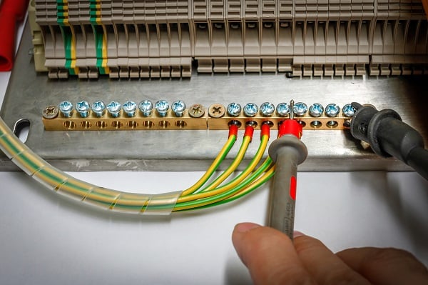
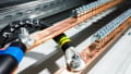
Figure 1. Ground distribution bus bar. Image used courtesy of Adobe Stock
Conductor Size Based on Branch Circuit Protection Device
As may be expected, the size of the conductor and the terminal(s) to accommodate the conductor(s) is based on the maximum allowable current to the field device; it is not based on the expected operating current of the field devices. Every branch circuit will have an overcurrent fuse or breaker sized beyond the maximum anticipated load current. It is this overcurrent protection rating that determines the grounding conductor size (Chapter 15.1 / Table 15.1).
Table 15.1 lists the specific size for each current, from a minimum of 15 amps, providing a wire no smaller than 14 AWG (for copper) and 12 AWG (for aluminum). Since there is no current rating smaller than this, these are the smallest acceptable wire sizes for grounding conductors. The largest provisioned current in Table 15.1 is 6000 amps, requiring a ground wire size of 800 kilo circular mils (kcmil) for copper, and 1200 kcmil for aluminum. For some perspective, 1200 kcmils is almost 1 square inch of cross-sectional area, a very large wire.
Connection terminals must always be rated to accept, at minimum, the size of the conductor wire noted in Table 15.1, but it does not need to be larger (Chapter 15.1: Exception).

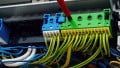
Figure 2. Ground conductor to bond panel door to main panel body. Image used courtesy of Adobe Stock
Chapter 16 - Grounding for Transformer and Power Supply Secondaries
There is much debate over DC power supplies and whether the output (-) of the supply should be bonded to ground. Unfortunately, the UL 508A specification does not rule for or against this practice in all situations. However, it does provide guidance for many cases as per the 2018 and later versions of the publication. All of the following pertain to output secondary circuits that directly feed field wiring terminals.
Output Less Than 50 Volts
If the 24 VDC supply (or any supply/transformer with an output less than 50 volts) is supplied with any voltage above 150 volts to ground, the secondary must be grounded (Chapter 16.1.a.1).
This means that if you provide this supply with 240 VAC where one leg is grounded, or if you provide a 3-phase 480 volt input, the secondary must be grounded, as both of these situations will yield a voltage above 150 volts.
Using a high-leg delta supply, either low or high voltage will always have at least one conductor exceeding 150 volts AC. A high-voltage wye with a grounded neutral will also exceed 150 volts on every conductor, so in these supply situations, the secondary must be grounded.
When, then, is the ground conductor not required?
A power supply with a single-phase 120 volt or a low-voltage 3-phase wye supply where the neutral is grounded do not need a secondary ground as the maximum conductor voltage is below 150 volts. Likewise, in a 240 volt single-phase system, if the neutral is grounded, then neither conductor will exceed 150 volts to ground, and this does not need a secondary ground.
However, even if the supply voltage is small, if it is ungrounded, then the power supply secondary must be grounded (Chapter 16.1.a.2). This guideline does not distinguish between AC or DC sources, so a power supply that uses an ungrounded DC input must also be grounded at the secondary side.

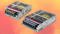
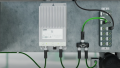
Figure 3. Power supply with an input below 150 volts AC. Image used courtesy of Adobe Stock
Output Greater Than 50 Volts
When the output exceeds 50 volts, it is likely that the device in question is a 120/240 VAC or 3-phase transformer, or it is a DC supply for larger field equipment (motors, actuators, etc.). In either case, the secondary should be grounded as long as the maximum voltage to ground is less than 150 volts.
For those 3-phase transformers with 4 wires, the midpoint of the wye (neutral) or the center of one winding in delta (also the high-leg neutral) is to be grounded.
All Other Cases
Any transformer or power supply that doesn’t need a grounded secondary according to these rules, but still outputs more than 100 volts must have a ground monitoring circuit with an audible or visual indication of ground faults, as long as the field wiring permits such an installation.
Grounding for Transformers and Power Supplies
The debate over grounding power supplies is likely to be ongoing, with some engineers preferring the removal of ground loops and ensuring isolation by keeping DC power supplies ungrounded. Others, in accordance with established standard practices and an observed lack of common adverse effects, ground all DC (-) supply connections, regardless of the voltage output ratings.
Whichever camp you fall into, be sure to create safe situations by following the regulations when possible, and for those unaddressed or legacy cases, consult experts who understand the side effects and preventions for common signal issues and hazards.
Featured image used courtesy of Adobe Stock
Related Content