Facebook
 Google
 GitHub
 Linkedin
How to Determine Choked Flow in Control Valves
Improper sizing and flow properties in a fluid system can cause choked flow, resulting in a loss of performance, or system damage. Prevention or correction are critical to a long, reliable service life.
What is Choked Flow?
Choked flow within a control valve is when the flow will no longer increase with a drop in pressure across a valve or orifice, due to cavitation within the valve body. A choked flow situation typically occurs in a system with constant pressure and flow on both sides of a valve. A pipe with equal pressure on both sides of a valve or orifice will have no flow, but if the pressure is reduced on the downstream side of the valve, there will be flow from the high-pressure side to the low-pressure side.

Figure 1. An example schematic of no flow.

Figure 2. An example schematic of flow.
Every valve, whether in a liquid or gaseous system, has some level of restriction. That level of restriction is referred to as the valve’s Cv. We can calculate the flow through a valve using the following formula.
$$Q=Cv\sqrt{\frac{\Delta{P}}{SG}}$$
Suppose we use water with a specific gravity of 1.0 and a constant for the Cv. We can see that, as the pressure delta (pressure difference in the upstream and downstream sides of the valve) increases, so does the flow. Because the flow can’t increase into infinity, it must reach an equilibrium or a choked flow scenario.
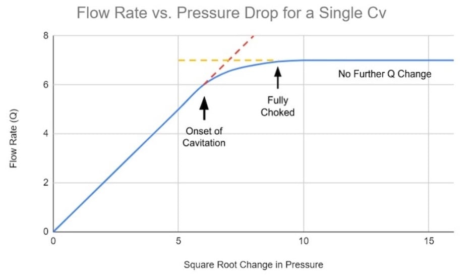
Figure 3. Chart showing the correlation between flow rate and pressure drop.
If the pressure drops below the vapor pressure of the pipe’s fluid, bubbles will form in the fluid. These bubbles will take up more room in the valve body, causing restriction. This is also the point where the flow no longer increases and reaches an equilibrium.
Reasons for Designing Around Choked Flow
A choked flow can be damaging to some devices like flow meters, valves, or pumps. When bubbles are within a liquid, those bubbles can cause cavitation within the pump, and flow meters won’t be able to provide an accurate flow measurement.
Most of the cavitation will occur at the most restricting point within the valve, known as the vena contracta, and some of these bubbles will be elevated once pressure is restored downstream. If the cavitation is significant enough within the valve, damage can occur to the valve body; and if enough damage occurs, the result will be leaks throughout the valve body.
Detecting Choked Flow
When determining if you have a choked flow situation, noise and vibration can be your first indication. Depending on the valve’s size and flow, the cavitation within the valve body can be loud and violent enough to cause excessive noise or vibrations within the pipe.
The installation location may give an indication of choked flow as well. If the valve is installed at a higher elevation than it was designed for, then the inlet pressure may be lower than the design pressure, which can cause a large pressure drop resulting in valve cavitation.

Figure 4. Cavitation damage on a control valve. Image used courtesy of Emerson
Another way to determine if you have a choked flow situation is to measure the flow or pressure drop across the valve, then look up the Cv for that valve. You now have all the variables in the above formula and can calculate your theoretical flow rate across the valve. If your measured flow rate downstream of the valve at the designed Cv setting is less than the calculated flow rate, you may have a choked flow scenario.
Most valve manufacturers provide a valve sizing chart listing the max Cv for a particular valve. The company may even list the choked pressure drop. If the pressure drop is greater than the listed choked pressure drop, then you may need to adjust the valve’s Cv or the pressure entering it.
The design phase is the best time to determine a choked flow situation. Typically, the flow and pressure required before and after the valve and the valve’s Cv are known, so the delta pressure can be calculated to see if the selected valve will cause a choked flow scenario.
Resolving Choked Flow
Regardless of when you discover you have choked flow, whether during the design phase, in the field, or after years of service, there are a few ways to rectify the issue.
The simplest solution could be to reduce the incoming flow. This would also reduce the incoming pressure, resulting in a lower pressure drop. Reducing the flow can sometimes be simply changing a parameter on a variable frequency drive (VFD), or other speed control command that drives the pump.
Another solution could be to increase the downstream pressure, resulting in a lower pressure drop. If the system pressure can be safely increased, then the pressure drop across the valve will be reduced.
Sometimes, it is impossible to reduce the flow or increase the pressure, so the next option is to select a valve with a larger Cv value. This means replacing the current valve, which can be time-consuming if the valve is already installed in the field. If the system is still in the design phase, changing the valve size or type can be an easy solution.
Choked Flow in a Control Valve
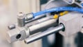
The main purpose of a control valve is to control the flow in a system. A control valve can be thought of as an orifice that changes size to accommodate different flow rates.
Any manufacturer provides a minimum and maximum Cv for the valve. It will be up to the designer to calculate the pressure drop with the required incoming flow and pressure at different Cv settings. The designer will also want to ensure that the valve will not cause cavitation at the minimum setting, just in case the valve was incorrectly installed or adjusted.
Featured image used courtesy of Kimray