 Facebook
 Google
 GitHub
 Linkedin
Introduction to H-Bridges for Industrial Motor Control
H-bridge circuits are commonly used to provide current switching capabilities to different electrical components in automated systems like motor control circuits, VFDs, and DC/AC current conversions.
Changing a single-polarity DC voltage into an alternating voltage has many uses, and the driving component behind this strategy is called an ‘H-bridge.’
What is an H-bridge Circuit?
An H-bridge circuit is commonly used in many applications, particularly in the automation and robotics industry. An H-bridge's overall function is to switch the polarity of current. The function of switching a current’s polarity finds many uses, including:
- DC to AC converters
- AC to AC converters
- DC to DC push-pull converters
- Motor controllers
- Bipolar stepper motors
- Inverters
- DC motor drives
With such a wide range of uses, knowing the applications of an H-bridge circuit and the basic principles around which they function can be beneficial in the design process.
The name "H-bridge" comes from the general shape of an H-bridge schematic. The schematic for an H-bridge at a basic level includes the load to be switched on the horizontal section of the “H,” surrounded by four switches on the vertical members of the “H” (see diagram).
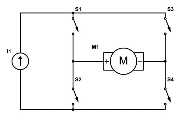
Figure 1. A basic H-bridge to create a reversible DC motor drive. Image used courtesy of the author
In a basic H-bridge like the one shown above, the load can receive a current of differing polarity through the use of the switches in the circuit. Using the numbering scheme in the schematic, we can see that when S1 and S4 are both closed, the motor will spin in one direction. When S2 and S3 are closed, the motor will spin in the opposite direction.
By design, neither the S1/S2 pair nor the S3/S4 pair may ever be allowed to close simultaneously. If both switches on the same side of the H (such as S1 and S2) were closed together, it would create a direct short across the power supply, potentially damaging the circuit or causing failures.
How Does an H-Bridge Work?
At its core, an H-bridge works by selectively closing two of the four switches to control the direction of the voltage across the load. Here's a quick breakdown of a potential motion scenario from the H-Bridge shown in Figure 1 above:
Forward Motion: Close S1 and S4.
Reverse Motion: Close S2 and S3.
Braking: Close S1 and S3, or S2 and S4 simultaneously (this shorts the motor terminals together and causes rapid braking).
Coasting: Open all switches, allowing the motor to coast to a stop naturally without active braking.
In real-world applications, these switches are never mechanical switches like the diagram shows. Instead, they are transistors like MOSFETs or BJTs that can switch on/off rapidly. Using these solid-state switches allows for finer control, faster switching speeds, and integration with microcontrollers or control circuits.
Common H-Bridge Uses
H-bridges are found in a wide range of applications, from small electronics to industrial motor controllers.
DC Motor Control
In robotics and automation, DC motors play a vital role in control system capabilities. They offer inexpensive and simple motion, widely used in everything from robotic arms to conveyor systems. H-bridge circuits enable DC motors to change directions and offer braking or motor coasting capabilities. By adjusting the way the switches operate, a controller can easily manage motor behavior.
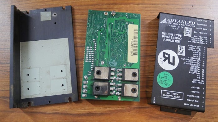
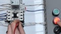
Figure 2. This DC motor speed controller uses four large MOSFETS (center at the bottom of the PCB). Image used courtesy of Control.com
Motor speed is varied by adjusting the duty cycle of the voltage applied to the motor. This technique, often called PWM motor control, is essential in applications where precise speed regulation is required. Robotics, drones, electric machinery, and more benefit from the power and flexibility of H-bridge motor control circuits.
Power Inverters
Most modern power inverters use some form of an H-bridge to change DC into AC. The H-bridge switches the DC at the frequency of the desired output (usually 50/60 Hz).
Switching the polarity via an H-bridge effectively creates AC power, although the resulting waveform would be a square rather than sinusoidal like traditional grid AC power. To create a more pure sine wave output, additional filtering stages with pulse width modulation (PWM) techniques are used.
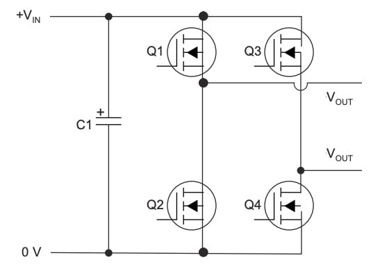
Figure 3. A basic H-bridge using MOSFETS to turn DC into AC. Image (modified) used courtesy of Texas Instruments
Inverters are used in renewable energy systems (like solar panels and wind turbines), uninterruptible power supplies, and electric vehicles, which all rely on H-bridge circuits.
AC to AC Converters
H-bridges can also be used for AC to AC conversion, changing AC power into a different form of AC power. One of the most common applications of this type of converter is in Variable Frequency Drives (VFDs). A VFD is used to control motor speed by altering the frequency of the AC power supplied to the motor. Typically, incoming AC power is first rectified to DC, then run through an H-bridge that pulses the DC power back into AC at the desired frequency when paired with proper inductive loads.
The H-bridge can be manipulated using pulse width modulation (PWM) to produce an output waveform closely approximating a sine wave. By controlling the output frequency, the motor’s speed can be precisely regulated, allowing for significant energy savings and better process control in industrial systems. It also allows for more precise motor control for automated processes.
DC to DC Converters
H-bridge circuits can also be used in certain types of DC to DC converters, a common device for efficiently stepping up or stepping down DC voltage levels. In these applications, the H-bridge, sometimes called a full-bridge converter, rapidly switches current through a transformer by alternating the direction of current flow through the primary winding. This bidirectional excitation magnetizes the transformer core in both directions, helping prevent core saturation while improving efficiency.
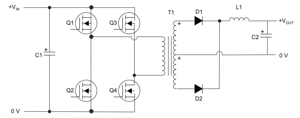
Figure 4. A full-bridge DC to DC conversion circuit, which takes advantage of a MOSFET-driven H-bridge (Q1 through Q4). Image used courtesy of Texas Instruments
After passing through the transformer, the resulting voltage is rectified and filtered to produce a steady DC output. This approach is common in systems like telecommunications equipment, battery-powered devices, and industrial controls, where both power efficiency and isolation are essential. The use of an H-bridge in these converters enables high-frequency operation and reliable handling of higher power levels.
Conclusion
The H-bridge is a fundamental circuit in the world of electronics, automation, and robotics. By allowing precise control over current direction and, by extension, motor rotation, H-bridges open up a wide range of possibilities for control systems. From basic DC motor control or complex variable frequency drives to high-performance inverters, the principles of the H-bridge remain the same.
Understanding how H-bridges work, their typical uses, and design considerations is a valuable skill for anyone working in electronics, embedded systems, or mechatronics. Whether you are building a small robot or designing an industrial motor controller, the H-bridge will likely be a part of your project.


It must be noted that each H-bridge switch has a freewheeling diode for the possibility of current flow when the switch is off.