Facebook
 Google
 GitHub
 Linkedin
Managing and Configuring Switches for Secure SCADA Networks
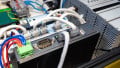
Network switches are the key components in the production network for secure communication and real-time data sharing between RTUs, PLC frontend servers, workstations, and HMIs.
Control and supervision of the machinery, including turbines, generators, exciters, transformers, and auxiliary systems, is the province of the plant control system in a power generation facility. The real-time operation, high availability, and asset security are key requirements of the power plant Industrial Control System, which depend on how resilient the production network is. A SCADA/DCS production network is a trusted zone for automation monitoring, controlling, and managing the critical equipment using OT and IT devices, where reliability and safety are high priorities for both infrastructure and humans.
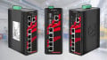
For small and isolated industrial control networks where a small number of control devices are connected, unmanaged switches can be deployed. In today's era, managed switches are commonly used in large interconnected networks because they offer advanced features and custom configurations as per site requirements, like traffic management, easy troubleshooting, VLANs, authentication, and authorization of users.
Network switches are the key components in the production network for secure communication and real-time data sharing between RTUs, PLC frontend servers, workstations, and HMIs. The typical control system may consist of networking equipment like routers, switches, firewalls, terminal servers, and KVM switches.
Typical Network Layout of SCADA System
The network industrial control system is different from the traditional IT/office network because of the operation requirements, such as real-time data handling, industrial communication protocols (Modbus, DNP, etc.), hardware/software redundancy, and lower latency for reporting critical alarms and trip signals in milliseconds.
In the large power generation, transmission, and distribution facility, the control systems (SCADA/DCS) pertain to multiple hierarchical layers by following the Purdue Model (ISA-95). This model was introduced in the 1990s by Purdue University to simplify the expansion and integration. The Purdue Model is a framework which breaks a system into multiple layers. The model is successfully implemented across multiple industries like energy, oil and gas, and manufacturing. It defines five layers, each one offering different functionality and control.
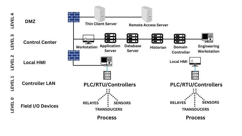
Figure 1. Typical network layout of a SCADA system.
Layer 0: Field Devices
This layer pertains to the field devices like sensors, transducers, transmitters, relays, and machinery that directly connect to the physical process.
Layer 1: Local Control
This layer contains PLCs, RTUs, and IEDs (intelligent electronic devices) for controlling the physical objects, processes, and logic by executing the program in real time.
Layers 2 and 3: Supervisory Control and Operations
Layer 2 provides the local monitoring and plant operations, and Layer 3 provides historians, web/file servers, and HMI (human machine interface) at the control center level. The layer-2 and 3 are sometimes combined in a single layer for small and medium plant facilities. The common nodes include SCADA/application servers, frontend servers, historian/archive servers, and workstations.
Layer 4: DMZ
The function of a demilitarized zone (DMZ) is to provide a secure data exchange between the IT and OT networks or with a remote control center, by deploying a firewall for traffic rules, an intrusion protection system (IPS), and an intrusion detection system (IDS).
Layer 4: Traditional IT network
This layer is for business operations, decisions, and intelligent tools and applications, such as ERP (enterprise resource planning).
After briefly discussing the control system hierarchy, it is pertinent to mention here that all the layers from top to bottom are interconnected through some sort of communication media (Ethernet/wireless) and network switches. Therefore, the role of industrial switches cannot be undermined.
The following industry best practices can be adopted to configure the managed switches installed at plant sites to secure the SCADA production network. The subsequent configurations will address the challenges of the production network, such as cyber incidents, unauthorized access, physical damage, and costly downtime of generation or transmission.
Console Port for the Initial Configuration
The console port is a physical port used to directly access the switch using a console cable (RJ45/USB/serial) connected between the laptop and the switch. This type of connectivity enables full control for initial configurations and can be performed through the CLI using terminal emulation applications like PuTTY, Tera Term, and telnet. The procedure is simple: connect the console cable between the laptop and a switch. As shown below, open the terminal and set the baud rate, data bits, and other parameters. The connection process to the console port is illustrated using the Cisco Packet Tracer tool.

Figure 2. The laptop connected to the switch via console cable. The example demonstrated using Cisco Packet Tracer.

Figure 3. The Cisco image and software version or build number appeared after booting the switch.
Setting the Console Port Password
Often, the vendor-specified default user account/password is kept in the OT/IT network. As a result, nodes are vulnerable to hacking. If someone has physical access to the switch and tries to connect to the console port of the switch, the set password on the “enable” command does not allow access to the switch settings. Using the following CLI commands, set the password for the line console 0 port. The password 1234 has been set.
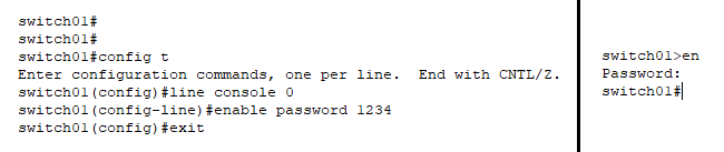
Figure 4. On the left side, step-by-step commands set a password. On the right side, when enable (en) is entered, the switch will prompt for the console password.
Remote Secure Connection
The limitation of the console port is that we must have physical access to the switch. In industry, the network switches are installed at distant fields and floors and it's not practically convenient to access the switch physically on-site. SSH is the recommended method to access the remote switch in the production network rather than telnet, which is not secure.
Management VLAN IP
Suppose the administrator wants to access and configure the network switch that’s used for protection relays, installed far away from the central control room or server room. For this, we need to configure the management IP for the switch for remote access from anywhere in the network. The important point is that the switch should be on the same network as the laptop or PG/PC.
The VLAN management is used for the switch management and the static IP address/subnet mask is assigned to the switch. For example, in our case, the switch VALN10 IP is 10.101.10.5/255.255.255.0 is configured. The group of nodes/computers/devices that are part of VLAN10 can remotely manage that switch through the VLAN interface.
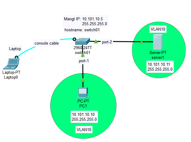
Figure 5. PC1 and server1 are part of VLAN10, thus allowing access to the switch using a specific VLAN.
The first step is to create a VLAN 10 and IP address using the following commands.
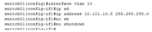
Figure 6. Commands that illustrate how to create VLAN10 and an IP address.
In the next step, add port 1 (PC1 connected) and port 2 (server1 connected) to the VLAN10 so that we can manage the switch through PC-1 and server-1 as well. The following commands are used to add switch interfaces, i.e., fastEthernet 0/1 and fastEthernet 0/2, to VLAN10. Both ports are configured in “access mode”.
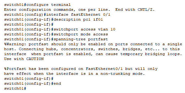
Figure 7. Adding port 1 to VLAN10.
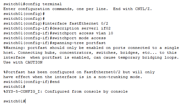
Figure 8. Adding port 2 to VLAN10.
Summary
In this first part of the article, we discussed the typical industrial control system and the hierarchical topology based on the Purdue model. The OT best practices are discussed here for securely configuring the switch in a SCADA production network, including the initial setup, console port password to prevent unauthorized access, and Management IP.
In an upcoming article, we will discuss SSH, HTTP/HTTPS, authentication against the Local Username, Cisco Discovery Protocol, and how to block unused ports.