Facebook
 Google
 GitHub
 Linkedin
Marvel Over DC Voltage: Permanent Magnet vs. Field Wound Motors
Since their creation, DC motors have become a part of our everyday lives. In this article, we’ll examine the differences between various types of field-wound and permanent magnet DC motors.
At some point throughout your day, whether you realize it or not, you probably use some type of DC motor. They are used in all sorts of everyday appliances ranging from beard trimmers, golf carts, industrial robots, and even your dishwasher.
DC motors have been around for nearly 200 years and have become invaluable and essential for our everyday lives. This article will explain the differences between permanent magnet and field wound DC motors.
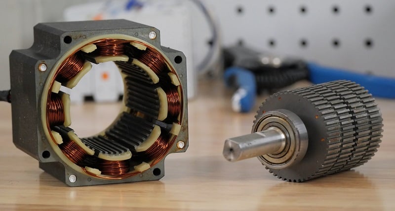
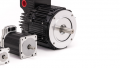
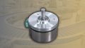
Figure 1. A small field-wound DC motor. Specifically, a stepper motor.
Basics of Industrial DC Motors
Let’s start this discussion with a foundation baseline discussion of a DC motor's operation without getting into too much theoretical detail yet.
Simply put, for a motor to rotate, a force has to be present to create the rotating motion. This is achieved through magnetic induction, which creates an electromotive force (emf) by interfacing two changing magnetic fields. To accomplish this, two main components in a motor are necessary: a stator and an armature.
Whenever we talk about a change in the magnetic force, think about it this way: A continually changing rotational force can only happen when the input force is changing. Within the motor, we don’t need to change both of the magnetic fields, only one. We might change the rotor windings only: this is a permanent magnet motor. We might choose to change both the rotor and stator windings: this is a field-wound motor. Alternatively, we might choose to change the field winding only: this is a brushless motor.
The field change is implemented through the use of the brush and commutator or other electrical controls.
Permanent Magnet DC Motors
With a permanent magnet DC (PMDC) motor, one of the opposing magnetic fields is generated by permanent magnets instead of an electromagnet. These magnets have alternating poles within the stator of the motor. The armature will generate the change in the field.
As seen in the figure below, we have a PMDC that consists of two magnets with a north and south pole (within a stator) and an armature in the center that consists of a rotor with windings These windings are connected to a commutator and two brushes that have opposite polarities.

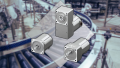
Figure 2. Motion within a PMDC motor is created when power is supplied to the brushes and the windings in the rotor are magnetized.
Advantages and Disadvantages of PMDCs
These motors tend to have some key advantages that make them ideal for specific applications, particularly at lower speeds. Due to the absence of field windings within the motor, PMDCs can be much smaller and tend to be much cheaper than their field-wound counterparts. Also, with no field windings within the stator, there isn’t a single specific arrangement for the rotor windings, which leads to more flexible rotor configurations and a lower manufacturing cost.
Permanent magnet DC motors face several disadvantages, particularly at high speeds. As the motor speed increases, so does the emf (voltage) forced back on the windings by the magnets, as the motor begins to act like a generator fighting against the supply voltage. Once the back emf approaches the supply voltage, there is no more control over the winding current and the base speed has been reached. Exceeding this speed requires a weakening of the field, introducing losses and lowering efficiency, especially at light loads. Faulty conditions are challenging to manage as well, as spinning motors can generate unintended currents, leading to torque ripple and overheating. Additionally, risks such as uncontrolled power generation during drive shutdown and potential demagnetization from inverter failures raise safety concerns.
Field-Winding Motors
While field wound motors and PMDC motors follow the same principle and use very similar components, the only real difference between these two motors is the way that the magnetic field is generated. With a field-wound motor, the magnetic field created from the stator is created through the use of electromagnetic windings.
One of the interesting benefits of a field wound motor is that different motor characteristics, such as torque and speed control, can be achieved depending on how the armature windings are connected. Field wound motor windings can be connected as series-wound, shunt-wound, or compound wound.
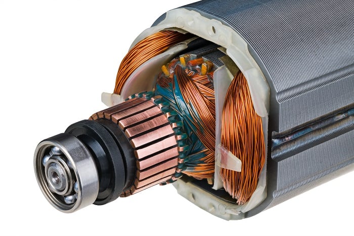
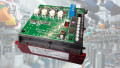
Figure 3. Within this field-wound motor, we can see the electromagnetic coils in the rotor and the two large field windings within the stator. Image used courtesy of Adobe Stock
Series Wound Motors
A series wound motor is a type of electric motor where the field windings are connected in series with the armature windings, allowing the field coils to receive the full current from the armature; see the figure below. This configuration is akin to how Christmas tree lights are wired together.
The advantage of this setup is that it creates a strong relationship between the field current and the torque produced, meaning that torque is directly proportional to the current over the entire operational range. Consequently, series wound motors can generate significantly higher electromagnetic torque, making them particularly effective for applications that require high starting torque, such as industrial machinery or heavy lifting operations, like cranes.
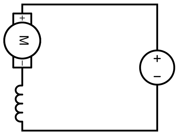
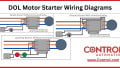
Figure 4. Circuit diagram of a series wound motor.
However, series wound motors are not without disadvantages. The lower resistance and higher torque on startup can lead to a higher current if the top speed is not quickly reached. Maintaining a long startup time can lead to motor overheating.
Shunt Wound Motor = Parallel Windings
Essentially, a shunt wound DC motor has the field windings and armature windings wired in parallel rather than in series. This parallel connection allows both windings to receive the same supply voltage, enabling armature and field current to flow independently.
One of the key advantages of a shunt motor is its ability to generate high torque, as the armature carries a higher current than the field winding, which has many turns to enhance flux linkage. Shunt-wound DC motors are typically intended to maintain a consistent speed despite changes in the load. This stability makes these types of motors ideal for applications in industrial machining, such as in mills or lathes.
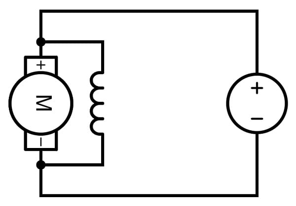
Figure 5. Circuit diagram of a shunt wound motor where the field and armature windings are in parallel.
However, a DC shunt motor also has some disadvantages. One significant drawback is its limited starting torque, which can be inadequate for applications requiring high initial torque to overcome inertia. Additionally, shunt motors may not perform well in scenarios where variable speed control is essential, such as in applications involving rapid acceleration and deceleration. Consequently, these motors are generally less suitable for tasks like electric vehicles or other dynamic load applications where speed and torque requirements fluctuate significantly. In summary, while the DC shunt motor excels in applications demanding consistent speed, it falls short in contexts where high starting torque and variable performance are critical.
Series + Shunt Windings = Compound Wound Motor
A compound wound DC motor is essentially a shunt wound and series wound motor combined into one. This design allows it to combine the benefits of high starting torque from series wound motors and good speed regulation from shunt wound motors. Compound wound motors are categorized into long-shunt and short-shunt types, which depend on whether the shunt wiring is across both the armature and series field coil (long shunt) or if the shunt wiring is only parallel to the armature winding (short shunt). Their ability to manage varying loads while maintaining a relatively stable speed makes them suitable for various applications, including large industrial machinery like presses and rolling mills, as well as conveyors, agitators, elevators, machine tools, and reciprocating pumps.
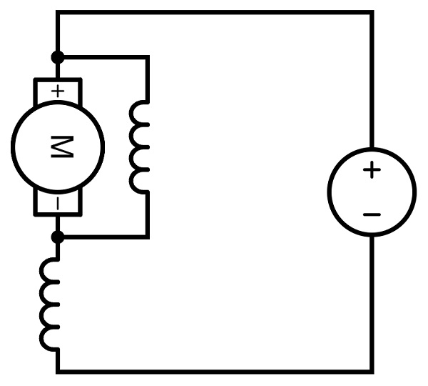
Figure 6. A compound motor is essentially a hybrid of a series and shunt motor.
Despite their advantages, compound wound DC motors also have some notable disadvantages.
Their starting torque is not as high as that of purely series DC motors, and their speed regulation is less effective than that of shunt DC motors. Moreover, the complexity of their design can lead to increased maintenance requirements. In some scenarios, different types of compounding, such as differential compounding, may limit their practical applications by reducing overall flux and performance, making them less favorable for certain uses when compared to series or shunt wound motors.
DC motors are essential components in various everyday devices, from household appliances to industrial equipment. This article examines the key differences between permanent magnet DC motors (PMDCs) and field-wound motors. PMDCs utilize permanent magnets, offering compact designs and lower manufacturing costs, making them ideal for low-power applications. However, they can struggle with efficiency and safety at high speeds. On the other hand, field-wound motors use electromagnetic windings, allowing for greater control over torque and speed through different winding configurations.