Facebook
 Google
 GitHub
 Linkedin
Motion Control Tutorial: Setting up a Linear Axis
Learn how to configure a single motion axis using Festo’s Automation Suite, a servo motor drive, and a simple electric linear slide assembly.
As we have seen many times before, it’s fairly easy to set up an introductory PLC program using nothing more than the PLC itself, a single push button, and the built-in I/O indicator lights.
Setting up a simple motion axis, on the other hand, requires a lot more careful input, even for just a simple bench test. In this article, we’ll set up a linear motion axis using the CMMT compact servo drive from Festo as a part of the recent launch of the developer kit that includes both the driver and a small NEMA servo motor.
Many of the elements in this tutorial would be common to all electric motion controllers. Still, we’ll pay close attention to the features of the Automation Suite configuration and control software.

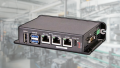
Figure 1. CMMT-ST servo drive controller.
Motion Axis Hardware
For most motion control applications that tie into a larger manufacturing process, a control (PLC or IPC) will be sending positional commands to the drive. These may be relative or absolute coordinate movements, as well as motion parameters like velocity and acceleration.
For this exercise, we will rely on built-in cycles of motion commands, and we will initialize them with the software application. This means that we will not need a PLC or digital inputs for this introductory exercise, only a laptop.
The newly released motion developer kit from Festo contains the CMMT-ST servo drive and an EMMT-ST servo motor, which is a NEMA 17 stepper motor with a built-in encoder.

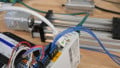
Figure 2. A ball-screw axis with a direct-mount motor (no gearing).
For my physical motion axis, I used a ball-screw-driven linear actuator with a working stroke of 400 mm. I also chose to include a physical stop button for the STO (safe torque off) inputs, but a simple jumper can also provide voltage to these inputs.
Festo’s Automation Suite
Automation Suite is the configuration app for many of Festo’s products, not just servo controls. Therefore, this process involves installing not only the software but also the plug-in for our specific device(s).
Installing Automation Suite
The installation of the software is straightforward. This navigation link contains the software product number. Clicking the first entry, “Comissioning, Festo Automation Suite,” will automatically download the .exe file.
Run the file to install. It should work on most Windows 10/11 PCs.
After the software is installed, immediately go to the Menu -> About link and check for updates.
Installing the Driver Plug-In
The plug-in can be downloaded from the product’s landing page, but the best way to obtain it is within Automation Suite. The Menu -> Repository link can ensure that you are downloading the most updated version.
Accessing “Repositories” will automatically open the plug-in window, including the CMMT-ST plug-in. Install it.
Firmware Update
Updating the firmware is also a very useful step, and it should be done before any parameterization or configuration. Updating firmware can result in a reset to factory defaults for some devices, so this step should be done at the beginning of your project.
Return to the main software window and click the magnifying glass icon at the top, the “Device Scan” section. The Device Scan is also available on the main opening page before a project is created.
As long as an active connection (Ethernet) is established, the device will be available. Click on the proper instance and click Firmware on the far right side. The top entry is the most recent version. You can click and install it, assuming it’s not already up-to-date.
Configuring the Drive and Axis
Upon creating and opening a new project, a wizard will guide the user through the setup. Most parameters can stay default, but a few of them will raise faults if mishandled.
First, we need to select the device's communication protocol. This CMMT is the MP version, which means “multi-protocol” Ethernet, EtherCAT, Modbus, and PROFINET.
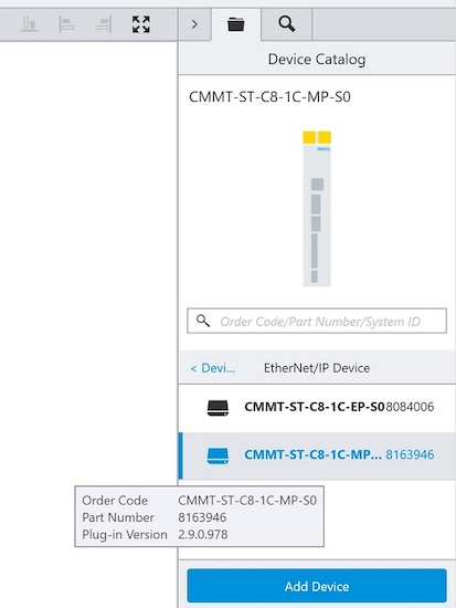
Figure 3. Adding the right device to the project.
Select Ethernet/IP on the right side, Add Device, and double-click on the new device. Wait for the plug-in to initialize and start. Click on the blue IP address path in the upper left, and you will be able to select the active device (as long as you are physically connected to port X18 and on the same subnet).
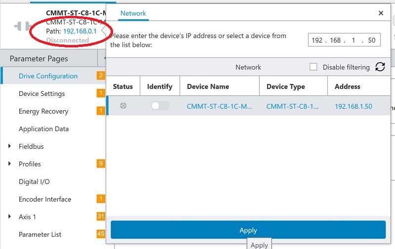
Figure 4. Choosing the right IP address.
Now, we need to input the specifics of our own motor and drive unit.
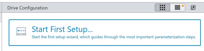
Figure 5. Starting the first setup wizard.
Start a new ‘First Setup,’ and for each segment of the project, adjust the following parameters:
- The drive unit is powered by 24 volts or 48 volts; for this simple setup, the same power supply is used for drive and motor power. If 48 volts is selected for the motor, it will result in a motor braking power fault. Also, enable control via the plug-in so that we can control it right from the PC screen.
- Select the proper motor. With the developer kit, this is already a Festo motor, and the part number can be entered directly.
- The drive motion needs to know the distance traversed by one full revolution of the motor and the total stroke of the axis.
A recommended method for calculating the distance of one revolution is to make a small pen or scribe mark at the edge of the motion carriage, then revolve the shaft once by hand and make a new scribe mark. Measure the distance between marks with a caliper. The total stroke is simpler and can be measured with a tape measure if it’s not known.
- Any gear or belt speed ratios must be provided. The travel speed will be affected by any ratio changes.
Once any changes have been made, press the “Restart Device” button and save all changes to the device.
At this point, you should be ready for motion! To set the stage (ensure the proper direction of travel and the speed), navigate to the “Control” tab “Manual Movement” and check the “position actual value.” Carefully rotate the ball screw by hand and ensure that 0.0 mm places the mover very close to the motor end, and as the mover slides away from the motor, the actual value should increase in the positive direction.
For very basic electric control from the PC, we need only to complete the following steps:
- Press the buttons to enable "Plug-in Control" and "Powerstage" at the top.
- Pressing the Jog -/+ buttons should move the axis!
We can also home the axis, which will, by default, bring it to the 0.0 mm position, so we need to ensure that this 0.0 position is indeed close to the motor end of the axis.
If you need to adjust the position for this initial setup manually, you can disconnect the motor shaft coupler and rotate the ball screw by hand. Once the current position is 0.0 and the mover is exactly where you want it, simply re-attach the coupler.
Next Steps in Motion
Stay tuned for the next article covering the process of creating cycling motion and viewing plots of the motion parameters, which is very useful for troubleshooting.
All images used courtesy of the author.