 Facebook
 Google
 GitHub
 Linkedin
PLC Programming: Best Practices for Function Block Diagrams
Function block diagrams can be a useful tool, but they can also add a lot of complexity. Learn about the what, when, where, and why of function block diagram (FBD) programming.
A Quick Review of FBD
As mentioned in previous articles, function block diagram, or FBD, is an IEC 61131-3 standard language used in PLCs to control processes based on sensors and results from the use of graphical blocks that describe functions rather than statuses of individual devices.
An FBD-style program can be a very useful tool to describe a high-level process and can be constructed rather quickly, but it can also become an overly complex mess of function blocks and logic gates. In this article, I’ll outline how you can make clear, concise FBD programs that are easy to read.

Figure 1. Large processes, like this grain processing plant, can make use of function block systems that transfer data more seamlessly between sub-processes. Image used courtesy of Adobe Stock
Less Is More
Within a PLC program, you can have multiple FBD routines that are called in parallel or in series, this allows you to make smaller routines that break up your code and process. Reviewing or trying to understand someone's code can be difficult, especially if there are many different processes happening at the same time.
I like to use the “less is more” technique when I’m structuring my code. I’ll break the process down into smaller sub-processes that may utilize five to ten function blocks, and each sub-process will only contain one unique task. The exception to this rule is if one sub-process is very small, I might group it with other small processes.
Sometimes, this style is simply not achievable because the overall process is small or the controller doesn’t allow for multiple subroutines. In this case, I’ll use comments and spaces between the processes to clearly define the different processes.

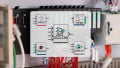
Figure 2. Organization of FBD subroutines within the Studio 5000 environment.
Handshakes
Function blocks should always have at least one input and output; one of those outputs should be a complete or done bit, and one should usually be an error bit. This way, you can track the status of your function block and report any alarms if need be. For example, if you have a function block that interfaces with a third-party device and the trigger is set, but the done bit is not on after five seconds, the system should fault and trigger an alarm code to the HMI.
It's important to know the status of every function block from a high level. This can be critical for troubleshooting the origin of a problem in the system, however you may not want to report a unique alarm for each function block. For many errors, the process should simply stop and a generic alarm should be shown.
Visual Appearance
It may seem trivial to spend time making sure all the lines, flags, and FBs are neat and organized, especially if you are the only one who is reviewing the code. But, one day in the far future, you may need to review this code, and it will greatly help if you have spent the time to organize it properly.
In most programming IDEs, the graphics used to represent variables (memory, I/O devices, integers, etc.) are called flags, and lines represent connections between the flags and the function blocks. These flags and lines can be stretched and moved so that your diagram looks neat and organized. Leave lots of room between function blocks so that connections from other function blocks can join to the inputs or outputs later, if needed.

Figure 3. Function block diagram example. Author’s image, created with Connected Components Work Bench (CCW)
When Should I Use an FBD?
Some control systems don’t really give you a choice, such as the Siemens Logo PLC. It does have the option to use ladder logic, but FBD is its primary language. Other control systems will allow you to create FBD subroutines alongside ladder logic, structured text, and even sequential chart diagrams.
An FBD can really be used in just about any scenario but they work best when working with processes that rely on timed events or analog sensors. A common use is temperature control. When controlling the temperature of a water tank, you might have a heating cycle, a cooling cycle, a PID, and analog conversion. These function function can all be their own function block with the diagram connecting them together.
Many ladder diagrams actually already contain function blocks (for example, timers, counters, math, bit operations, and many others), the main difference is the connection of inputs and outputs, no longer existing in unique horizontal ‘rungs’.
Where Should I Use an FBD in My Program?
The best place to use an FBD is at the highest level of the process. Think of the FBD as a conductor of an orchestra. The FBD commands and feeds information to all the other smaller processes, but the FBD still has only one main process.
In our water tank example, the purpose of the main process is to maintain the temperature of the water for one tank. If I had multiple tanks, I would create another FBD that would bring together all the water tanks’ temperature control. Combining processes this way allows for easy-to-read and understand function block diagrams.
Programming for Every Situation
Programming PLCs is somewhat related to traditional programming. Although people may prefer one language over another, each one has strengths and weaknesses, designed for particular circumstances. For modern processes, it’s impossible to focus on only one IEC language and ignore all others for the entirety of the system, making the learning of others like FBD, ST, and SFC all very valuable for a modern manufacturing skill set.
Want to put it to the test? Here's an example tutorial of a PLC that uses FBD programming
Featured image used courtesy of Adobe Stock
Related Content


There is no complexity difference between FBD and Ladder. They are both boolean logic. The only difference is the editor. Schneider Electric is a much better editor as you just double click on the pin and the program Control Expert brings up the list of filtered tags. Double click on the tag and it is assigned. No adding a tag with a connection to the black as in Rockwell’s Control Studio. I figure I can program 80% faster with Schneider’s product than with Rockwell’s.