Facebook
 Google
 GitHub
 Linkedin
Pneumatic Cylinders Used for Industrial Automation
Engineers face a common challenge of moving objects from one point to another, especially in a production line. This article will introduce the pneumatic cylinder as used in industrial automation.
Industrial automation involves the movement of goods automatically within the production line, equipment, and machines. Such movement is made possible through the use of various motion devices like robots, conveyor belts, gears, shafts, cylinders, etc.
Cylinders have always been involved in positioning, clamping, and transmitting parts in automated systems. Some of the most common cylinders are hydraulic cylinders, making use of fluids such as oils to achieve the task, and pneumatic cylinders, using compressed air to perform the expected task.
For those who need a brief primer on pneumatic cylinders, this article will describe some of the basic features of operation, as well as describe the types of cylinders and the operating principles, aiding an engineer in learning which cylinder may be the right device for an application.
What Is a Pneumatic Cylinder?
Pneumatic cylinders, commonly referred to as air cylinders or pneumatic actuators, are industrial automation components that use compressed air to create linear reciprocation motion used for positioning, clamping, and transmitting products within the industrial setup.
It is an economical mechanical method since it does not require the use of driver circuits as electrical actuators would need. To build or maintain an effective pneumatic industrial system, an engineer is expected to have an in-depth knowledge of the cylinders and the factors for cylinder selection. Figure 1 shows some of the pneumatic cylinders used for industrial automation.
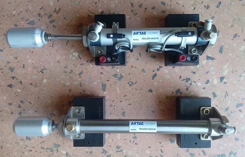
Figure 1. A small selection of pneumatic cylinders. Image courtesy of the author
Pneumatic Air Cylinder Components
Figure 2 below is the representation of the parts of the pneumatic cylinders.
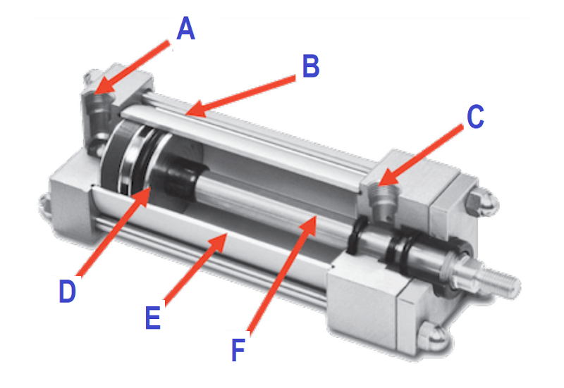
Figure 2. Parts of the pneumatic cylinder. Image used courtesy of Inst Tools
- A- Cap-end port allowing air to enter for cylinder extension
- B- Tie rod (optional) to hold both ends of the cylinder together under pressure
- C- Rod-end port allowing air to enter for cylinder retraction
- D- Piston with airtight seal, providing motion in the presence of pressurized air
- E- Barrel casing to contain the piston and pressurized air
- F- Piston rod, usually fixed with a thread or linkage at the end
Types of Pneumatic Air Cylinders
In industrial automation, the technology employed uses three common types of air cylinders: single-acting, double-acting, and telescoping pneumatic actuators. Each type of pneumatic cylinder has a specific purpose, and the engineer must select the best suitable cylinder for the intended task.
Single-acting Pneumatic Cylinder
This type of cylinder has a mechanism that works only on one side of the piston. This means the compressed air is connected to drive the piston in a single direction. At the same time, a mechanical spring is utilized to move it in the other direction, hence, completing the reciprocating movement. Figure 4 below is an image of a single-acting pneumatic cylinder.

Figure 3. Single-acting pneumatic cylinder. Image used courtesy of the author
Single-acting pneumatic cylinders are classified into either pull-type or push-type single-acting pneumatic cylinders.
Pull-type Single-acting Pneumatic Actuator
The working principle is compressed air pumped into the system to pull the piston into the cylinder when passing the compressed air through the cylinder pressure port—then the piston retraction is activated. See Figure 4 below.
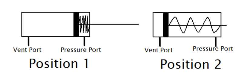
Figure 4. Pull-type single-acting pneumatic cylinder. Image used courtesy of the author
Push-type Single-acting Pneumatic Actuator
Here the mechanism works such that compressed air is pumped into the cylinder and pushes out the piston while the spring mechanism is employed to retract the piston back into the initial position when the compressed air is removed. See Figure 5 below.
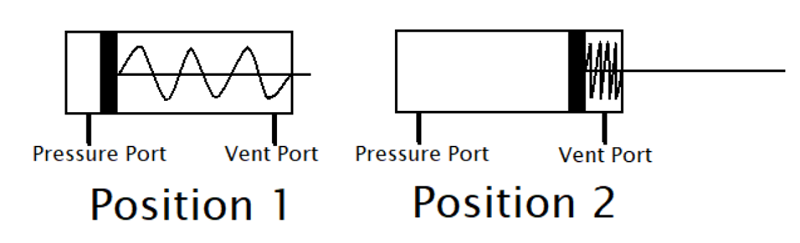
Figure 5. Push-type single-acting pneumatic cylinder. Image used courtesy of the author
Double-acting Pneumatic Cylinder
Unlike the single-acting pneumatic cylinder, where only one side is supplied with compressed air or pressure, the double-acting pneumatic cylinder works under a principle where air is supplied on both end sides of the cylinder; through the cap-end port and the rod-end port. This type of air cylinder is preferred in most industrial automation systems because it completely controls the movement of the piston using compressed air.

Figure 6. Double-acting pneumatic cylinder. Note the pressure ports at both the right and left ends of the barrel. Image used courtesy of the author
Working Principle of Pneumatic Actuators
The types of pneumatic cylinders discussed above have different working principles. Here we will analyze the working principle of each type of cylinder.
Single-acting Cylinder Working Principle
As discussed above, this type of cylinder has connected pressure driving the piston in one linear direction, while a mechanical spring controls the movement of the piston in the opposite linear direction. See Figures 4 and 5 for all the possibilities where the mechanical spring retracts or extends. This type of cylinder is used in applications where the piston should be in a certain location once the pressure is lost. They have a disadvantage of the spacing due to spring length, and this has to be countered by increasing the cylinder length to counter the space utilized by the mechanical spring.
Double-acting Cylinder Working Principle
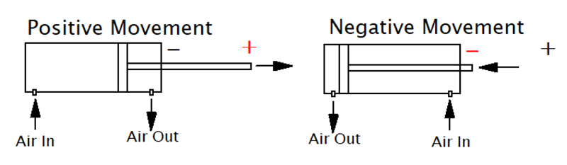
Figure 7. Working mechanism of a double-acting cylinder. Image used courtesy of the author
Figure 7 above shows the movement of the piston when air enters the cylinder’s cap-end and rod-end ports. The negative movement position occurs when the piston is retracted, and the positive movement position occurs when the piston is extended.
When pressurized air enters through the cap-end port, it pushes the piston outward, extending its rod, as shown in Figure 7 (left), while air is simultaneously forced out through the end-rod port.
For the retraction of the piston to occur, compressed air is forced into the rod-end port pushing air out through the cap-end port, and allowing the piston to move back to the negative position as shown in Figure 7 (right).
Double-acting cylinders have full control and a bigger piston stroke since the compressed spring does not consume a portion of the inside volume. However, they cannot be employed in applications that need a known de-energized position since, in the case of compressed air loss or leak, they will be free to move however the force of the load determines.
Selection Criteria for Air Cylinders
Below are the important specifications used while selecting a pneumatic cylinder:
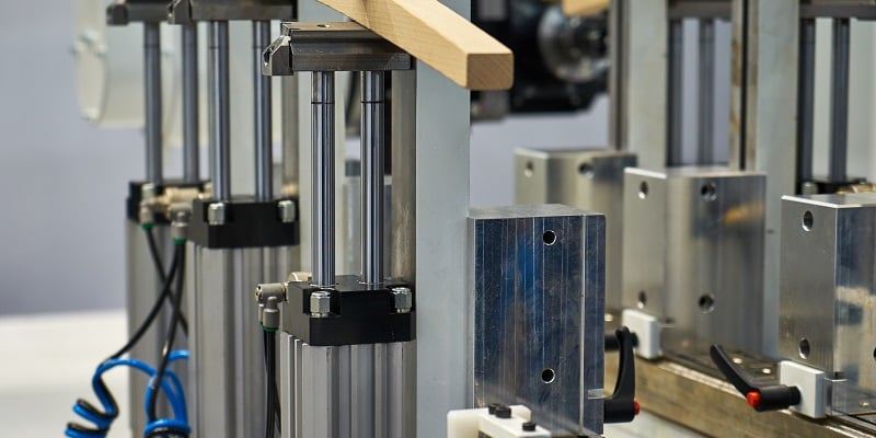
Figure 8. Many industrial systems rely on air cylinders. Image used courtesy of Adobe Stock
The Diameter of the Cylinder
The pneumatic cylinder’s internal piston diameter determines the amount of mechanical force the cylinder can generate from the applied compressed air. While working with a single-acting cylinder, ensure you take into consideration the mechanical spring opposing force.
The formula below is suitable for use in double-acting cylinders with no opposing spring force.
$$ F = P \cdot A - f$$
Where
F = Force of the cylinder
P = System air pressure
A = Piston area (for retraction, subtract the area of the piston rod)
f = Friction drag, while in motion
Length of the Stroke
This will ensure the piston retraction or extension achieves the required length. Note that the longer the piston rod, the higher the stress on the cylinder rod and the longer the cylinder. A long cylinder, coupled with a large piston diameter, creates a large volume of air, and the speed of motion will be reduced.
Selecting an Air Cylinder
Engineering a pneumatic system can be simpler than some electrical systems without the need for switches, dangerous voltages, and controllers. But there are many other external factors to consider while selecting a pneumatic piston, including port connection size, cushioning, mounting style, system operating pressure, and position feedback to design a truly efficient and effective pneumatic system.
Related Content