Facebook
 Google
 GitHub
 Linkedin
Shunt Resistors and Applications in the Field of Instrumentation
A shunt resistor connects in series with a load to measure the high current in the DC circuit. Using Ohm's law, the current value can be calculated by measuring the voltage across the shunt.
Measuring current can be a dangerous task in DC circuits because it involves placing the meter into the electrical flow, exposing the circuitry to potentially dangerous current. The shunt resistor is used to prevent this risk and measure high currents without requiring robust meter conductors.
What is a Shunt Resistor?
A shunt is a resistive element (resistor) in a DC circuit that allows current to circulate from one point to another by creating a low-resistance path. The practical usefulness of shunts in the power plant facility is to measure the high current in the DC circuit when it is impossible to directly connect measuring devices like analog or digital display panel meters to the DC line.
For the instrument engineer working in the field of plant data acquisition, the question is how to measure high current in an AC/DC circuit. In the case of AC, a current transformer (CT) is used to measure the amperage in large power systems. Shunts, on the other hand, are used to measure high currents in a DC circuit, such as the output current of a rectifier, battery charging or discharging current, etc.
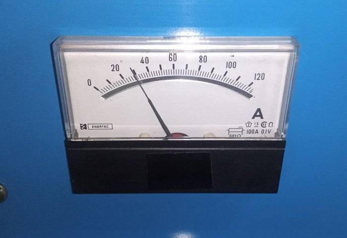
Figure 1. Conventional analog panel ammeter, having a shunt resistor rating of 100 amps at 0.1 volts.
As shown in Figure 2 below, the shunt has two conductors made of brass and copper, connected with a low-resistive manganese strip. The shunt usually has two large terminals and two small terminals. The circuit is connected to the large terminals, and the current goes through the rated strips between them. The small terminals across the shunt strip create the known resistance.
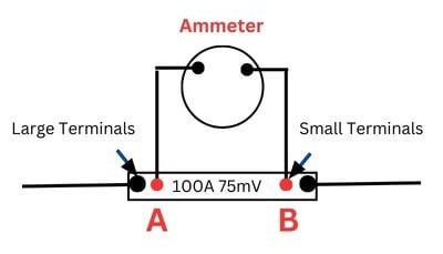
Figure 2. A typical shunt resistor is connected in series to load, allowing the current to be displayed by measuring voltage from ‘A’ to ‘B’ and dividing by a known resistance value.
When the shunt is made in the factory, it is calibrated and designed so that the physical current passes through it. It can decipher how much current has passed through it by taking the voltage reading between points A and B and using Ohm's Law with the resistance, as represented in Figure 3.
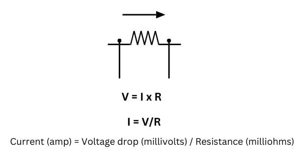
Figure 3. Ohm’s Law to determine current.
The rating of a shunt is usually engraved on the side of the shunt or displayed on the face of the meter, like 100 A and 75 mV. The 100 amp value indicates the maximum amount of current that the shunt can handle. The second value is 75 mV. This is the voltage that will be detected across the two small screws or points when 100 A current passes through the meter.
It is pertinent to make sure that when we use a dedicated analog or digital panel meter, the meter should match 100 A/75 mV because the display meters are calibrated based on the values of a shunt so that a panel meter, both analog and digital, can show accurate current readings.
Shunts of different shapes and sizes are available in the market and the low resistance (relative to the load) does not affect the flow of current in the circuit. The voltage drop across the shunt resistor connected in series to the load is virtually negligible compared to the load voltage. Any conductor, such as an ordinary resistor or a length of copper wire, could be made into an improvised shunt. The typical multimeter is useful for measuring resistance below 1 ohm, but it is not suitable for measuring the incredibly low resistance of the shunt, which makes the shunt’s conversion from voltage to current very useful.
The very low resistance of shunts produces a large current, limited only by the load device. If you continuously pass a large amount of current through them, they produce some heat, so a properly-rated shunt is essential.
Connection of Shunt Resistor with Ammeter
The meters and instruments are key devices to measure the momentary values and report the key electrical quantities of any power-producing plants and grid systems to the control center. Conventional powerplants have many analog and digital panel meters that show the AC/DC, voltage, and wattmeters.
The operating principle is the same for both the ammeters and voltmeters. The response to different quantities is obtained by using shunts for ammeters and series resistors for voltmeters.
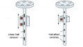
Figure 3 shows two identical operating mechanisms connected, one as an ammeter and the other as a voltmeter. Both mechanisms are designed so that 50 millivolts across the coil will give full-scale deflection. In this diagram, the ammeter is set in place to measure currents up to 100 amperes which is why its scale is marked 0-100 amperes. In other words, the shunt is designed such that when 100 ampere flows through it, it will give a 50 millivolt drop across the terminals, and such a shunt is known as 100 amperes 50 millivolt shunt.
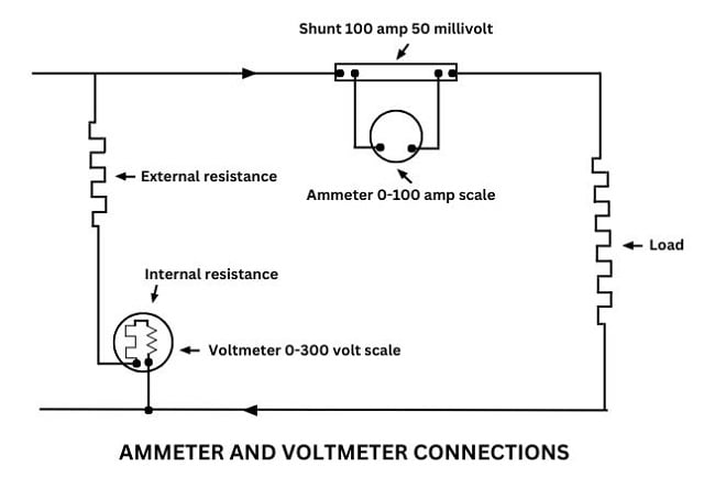
Figure 4. The operating principle is the same for both the ammeters and voltmeters.
For currents below 50 or 60 amps, the ammeter shunt can be mounted inside the instrument case, but for higher currents, the size of the shunt and the heat generated make it necessary to mount the shunt externally. Similarly, switchboard voltmeters up to 300 volts usually have the resistor mounted in the case. At the higher voltage, an additional resistor is mounted externally and connected in series with the internal resistance and operating mechanism of the voltmeter.
It is pertinent to mention here that the resistance of the connections between shunts, the resistors, and the operating mechanism must be taken into consideration in the design of the instruments.
Converting Current to Voltage for ADC and PLC
The direct current ammeters and voltmeters find their greatest field in measuring the current and voltage at which batteries are charged and discharged and in motor and generator excitation circuits. The shunts can be used in analog panel meters, digital panel meters, and with PLCs.
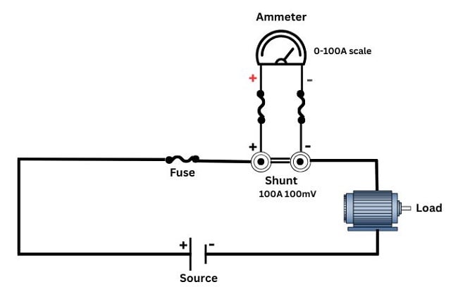
Figure 5. Shunt resistor connection diagram with load and panel meter.
A close look at the datasheet of the device in Figure 5 below, the output of the shunt is 0-100 mV. This small voltage signal is amplified using a DC voltage transducer having a 0-100 mV input range. The DC voltage transducer can output a 0-10 mA current signal, which can be further used in the RTU/PLC card for analog-to-digital conversion (ADC), to be processed for remote monitoring and control.
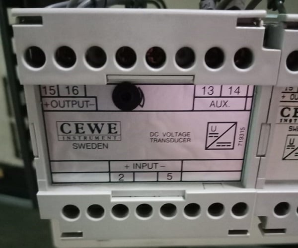
Figure 6. A voltage transducer having an input range of 0-100 mV, receiving mV drops across the shunt resistor and producing an output of 0-10 mA for a control system.
Benefits of Shunt Resistors
- Shunts are used for high-current applications, like monitoring of load current such as electric motors.
- It is very easy to measure the voltage drop and calculate the current using Ohm’s Law, as the voltage drop is proportional to the current passing through the shunt.
- They are usually small, lightweight, cheap, and available in various shapes, sizes, and ratings.
- They are used to monitor battery bank charging and discharging.
- Large diameters of wires are very expensive. The terminal of the shunt allows you to monitor the current using a small gauge wire.
- It does not generate much heat while 50 A or 100 A current is passing through it.
- It provides insulation and protects against short circuits and overloading.
- It has a good current measuring accuracy by having a known resistance value.
- Commonly used panel meters and energy meters, etc.
Featured image used courtesy of Adobe Stock, all other images used courtesy of the author