Facebook
 Google
 GitHub
 Linkedin
The One Where A Modbus Output is Controlled by Two PLCs
Get ready for a control-themed roller coaster ride, pitting two PLCs against one Modbus I/O rack, and you might be shocked at the results: Who will win… And who will lose?
I hate boring technical articles.
So today, we’ll mix a Modbus tutorial article with some basic protocol theory and learn why it’s really important to understand client/server relationships when critical equipment is on the line.

Figure 1. Modbus: who wins? And who loses? Image used courtesy of Adobe Stock
Setting the Stage
Previously, we described how to drive a Synergy Logic SLM remote I/O system via a CompactLogix PLC, and to our great relief, it was quite simple to implement.
Today, we’ll add a second PLC to the mix: an AutomationDirect Productivity2000. The tutorial portion will be very short because, once again, it’s really easy.
On my setup, I still have the CompactLogix PLC connected to the Modbus I/O system with the instruction running and enabled. I can read the inputs and write to the outputs.
Productivity Suite Modbus Read/Write
All we need is a Productivity PLC, of any series. If you are new to the platform, have a look at our intro tutorial article.
Be sure the Productivity is set to the same subnet as both the SLM system and the CompactLogix, and that they are all physically linked on the same network.
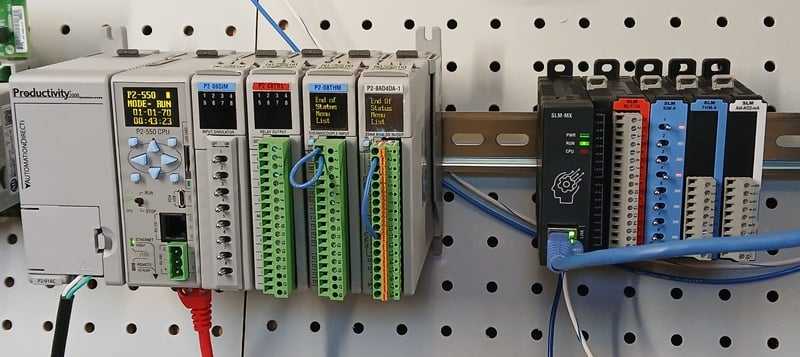
Figure 2. Productivity2000 PLC and SLM I/O system. Image used courtesy of the author
Just like in the Rockwell environment, no device needs to be added to the hardware configuration, and no EDS or Ethernet device config is necessary - you only need the IP address of the SLM-MX.
The Productivity Suite software contains built-in Modbus Read and Modbus Write instructions.
Modbus Read (MRX) is a structure-type tag, so you need to provide the following:
- The IP Address of the SLM-MX bus coupler.
- A structure name, like SIM_Module (since my module is a simulator input card with little toggle switches)
- Check the Automatic Polling button unless you have input logic to provide rising edges. In my example, I increased the polling time to 500 milliseconds, since I do not need high speed. Plus, it makes the whole problem far more exciting later.
- Set the Starting Address to 1, since the first address in our SLM system is 100001.
- The Function Code for reading multiple inputs is Code: 2.
- Create 8 non-array tags and give them logical names. Input_1 through Input_8 seemed like a reasonable assignment to me.
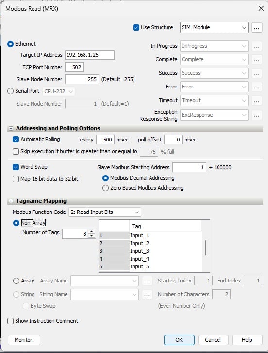
Figure 3. Productivity Suite Modbus Read (MRX) instruction parameters. Image used courtesy of the author
The Modbus Write (MWX) instruction is virtually identical except that we will use Function Code 15 for multiple coils, and this is a 16-terminal relay output card, so make 16 non-array output tags.
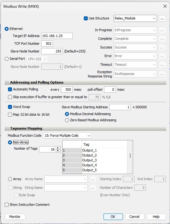
Figure 4. Productivity Suite Modbus Write (MWX) instruction parameters. Image used courtesy of the author
Download the program and be sure that the CPU mode is set to Run.
Verifying Operation
At the top of the ladder programming screen, press Monitor (the binocular icon). When you switch the inputs on and off over at the SLM simulator card, you should see the tag values reflected in the Modbus Read command!
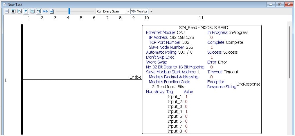
Figure 5. Monitoring the results of a Modbus Read instruction. Image used courtesy of the author
Switch over to the Rockwell platform, and verify that the tags also update at the same time.
This means that we can read information from one I/O system on two different controllers! Now, one can support logic, and the other can support an IIoT connection, or two separate machine centers can both read from one single infeed conveyor system!
Houston, We Have a Problem!
Reading inputs across multiple controllers is great - everyone can see important data.
But now, we’re going to flip to the outputs. In the Productivity environment, you can add some logic to drive the output tags, or add them to the Data View tab, check the Edit box, and Send Edits.
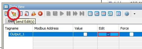
Figure 6. Sending a TRUE value to a digital output. Image used courtesy of the author
What do you hear?
Well, for me, since the CompactLogix is telling Output_1 to turn OFF, and now the Productivity is telling Output_1 to turn ON, they are fighting.
Since the poll rate of both is 500 ms, this output is clicking on and off like crazy! Sometimes it’s random, sometimes it’s a regular, half-second click. But either way… NOT GOOD.
Figure 7. Watch and listen (unmute) to the behavior of conflicting Modbus commands. Video used courtesy of the author
Modbus Multiple Clients
Let’s dig into this problem, and more importantly, how to solve it.
With client-server relationships, there are four main scenarios we could see:
- 1 server (the one responding to commands; the SLM system) locked to 1 client (the one giving the commands; the PLC)
- Multiple servers locked to 1 client
- 1 server controlled by multiple clients
- Multiple servers all controlled by multiple clients
The final two of these scenarios, multiple clients (PLCs), present the problem. I imagine you can immediately see why. Conflicting commands from two clients will cause intermittent or delayed responses, and this is unacceptable.
Modbus, by default, does not include a read-only option, wherein both PLCs can read inputs and outputs, but only one is the owner that can drive the outputs.
So what is the solution??
With Modbus, the solution comes down to strategy.
Here are the two brief points to consider:
- Multiple PLCs reading any data is just fine (function codes 01, 02, 03, and 04)
- Only allow one PLC to write data to any one output (function codes 05, 15, 06, and 16)
There is one lower layer to consider, even when reading inputs. When we consider the polling intervals, Modbus TCP always processes the first message, then the second - even if the first action hasn’t been completed. For this reason, if the messages arrive with a relatively long delay in between, you may see the two actions performed distinctly (click ON and then click OFF). However, if the messages arrived at right about the same moment, there may only be one click, whichever command arrived second. If the previous state and this new state are the same, there may not even be a click at all, and it would appear as though the command was skipped.
So, here is the foundation of a logical strategy:
- Assign distinct, unique names to each real-world I/O connection, and these names should be used across all controllers.
- Determine which controller should be the driver of which real-world I/O connection. This is a global decision across all controllers.
- Document this I/O map and, with whatever power exists in you and in your company SOP, make it known to all your PLC users.
Putting Modbus to Work
It may be one of the oldest industrial protocols in existence, but Modbus isn’t going away. Its simplicity and built-in integration into nearly every controller means that we can rely on this consistent, low-level method of transferring I/O data across PLCs and across generations.