 Facebook
 Google
 GitHub
 Linkedin
Tutorial: First PLC Program with a Beckhoff IPC
These days, the industrial PC (IPC) is changing the way that engineers approach control logic solutions. Learn how to set up a basic project in a Beckhoff IPC using structured text programming.
We must begin any IPC tutorial with a few basic definitions for those who are new to this concept of industrial PCs. Many control engineers have a background that mainly involves PLCs, which have been the reliable workhorse of manufacturing for decades. The purpose of the new evolution to PC-based controls is not to usurp tried-and-true logic but to provide more functionality, diagnostics, and instant connection to critical process data.
How is an IPC Different From a PLC?
The industrial PC is a fully functioning computer with an operating system, usually a version of Windows or Linux, just like your laptop. Beckhoff IPCs can also run the TwinCAT/BSD operating system, which is based on the FreeBSD standard. IPCs designed for control scenarios also include software with a separate runtime that performs the logic commands linked to the physical I/O, just like any traditional PLC. This runtime is what sets it apart from a normal laptop. It allows you to run programs, or even the development environment, without affecting the PLC control of the real-world field devices.
Typically, a PLC is installed in a control cabinet, and a laptop with the programming IDE is located nearby or tethered via a network cable. With an IPC, this could still be accomplished in the same manner, but alternatively, the IPC can run the keyboard, mouse, and monitor, with all programming accomplished directly on the IPC. This is more common in training or starter kit scenarios, and users should note RAM requirements to ensure speed and performance meet expectations.
This onboard programming method is the path we will illustrate with this Beckhoff IPC tutorial
Beckhoff C6015 Hardware Setup
To build an effective control logic example, we need a few real-world I/O devices.
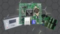
Our hardware arrangement is the new starter kit from the Beckhoff USA training department that’s available for purchase in the U.S. This kit includes the C6015 compact IPC with an assortment of I/O modules interfaced with an EK1100 EtherCAT coupler. Specifically, the modules consist of 2x digital input, 2x digital output, 1x analog input, and 1x analog output. In this kit, there are 6x pushbuttons, 6x LEDs (inside the illuminated buttons), 1x potentiometer, and 1x panel voltage display.

Figure 1. Beckhoff’s new IPC starter kit
If you don’t have the kit, no problem; this tutorial can be accomplished with any assortment of digital I/O since the IPC is the main driver of the project. Our example program will include simple reading and writing of digital devices, paving the way for analog I/O and more advanced functions after that.
Step 1: Connect and Power the IPC
The first step is to connect the field devices to the I/O terminals and provide power to the bus coupler. Power is also connected to the IPC and a network cable links LAN1 (X102) of the IPC to LAN1 IN (X1) of the bus coupler.
Although the CPU is isolated from the physical I/O modules, we can imagine this cable just like the backplane of any typical PLC chassis with local I/O. The port allows us to scan and automatically discover any I/O modules connected to the coupler as if they were modules in a chassis alongside the CPU. In this way, we can reach out and discover multiple remote I/O cabinets, all with a single scan; there is no need to discover and add each one individually.
Attach the keyboard and mouse to the USB ports and monitor to the DisplayPort. Finally, turn on the power to the IPC and the I/O modules.
Step 2: Access TwinCAT XAE (Engineering IDE)
On first power-up, the Windows environment will guide the user through any normal PC setup, prompting for a username, password, and network credentials (if Wi-Fi is enabled or a USB dongle installed).
In most shipments, the required software is pre-installed on the IPC. If not, the next step will be downloading and installing the TwinCAT Package Manager to then download and properly install TwinCAT XAE (the programming environment) and XAR (the runtime for the PLC to operate). There are several builds of TwinCAT 3, these instructions are for build 4026. For an older build, it is advisable to contact Beckhoff for assistance with the proper installation method.
Figure 2. Accessing TwinCAT XAE
Once installed, TwinCAT XAE shell can be opened from the menu in the bottom right corner of the desktop.
Step 3: Add I/O to a New Project
Start a new project in the normal fashion: File -> New -> Project, or the icon in the upper left. Give it a name and file location according to your operating standards.
Before writing the program, we should first define the hardware. Open the I/O menu in the project tree on the left sidebar, right-click on "Devices" and scan.
Figure 3. Scanning the I/O system for modules
The dialog will require you to select the network port with the I/O attached, and you can simply leave both options checked.
Once the scan is done, all I/O modules will show up under "Device 1" -> "Term 1". My network adapter is the EK1100 and is labeled as such.
Figure 4. Viewing the I/O module configuration
At this point, we can choose to test the I/O connections to be sure they work as they should. If the CPU is in Config Mode (the blue icon in the lower right corner), then we can activate Free Run with the toggle in the toolbar.

Figure 5. Toggling Free Run on/off to test I/O
Free run allows us to enter each channel and view or write the value of an I/O point.
Step 4: Designing a PLC Program
Now we can make a new PLC program from the left sidebar: PLC -> Add New Item.
Within this new PLC item, double-click on the MAIN task inside the Program Org Units (POU) folder. This new program (PRG) is, by default, a structured text program, so we will need to follow a careful syntax structure to define the variables.
Declaring and Linking Variables
In the main programming window, the panel is divided into two portions. The lower portion will contain our actual PLC program. Inside the top portion, between the VAR and END_VAR, we need to add the variables for I and O with the following commands.

Figure 6. Our initial variable list with 1x each: digital I/O and analog I/O
Bool inputs (buttons, sensors, etc):
Your_DigInput_Name AT %I* BOOL
Bool outputs (valves, contactors, etc):
Your_DigOutput_Name AT %Q* BOOL
Analog inputs (sensors, potentiometers, etc):
Your_AnlgInput_Name AT %I* INT
Analog outputs (speed control, panel meter, etc):
Your_AnlgOutput_Name AT %Q* INT
Once variables are declared, we need to "Build Solution" from the Build menu at the top (in this dialog, keep the Autostart PLC Boot Project checked). This build action creates the variables in the left sidebar. Now, these variables can be "Linked" to the actual I/O modules.
Right-click on each terminal’s channel "Input" or "Value", then "Change Link", and select the proper variable from the list (be sure to match the right I/O and data type). A small arrow icon will appear when the link is established.

Figure 7. Establishing the link between I/O terminals and program variable
After all the links are finished, "Activate Configuration" from the toolbar. In the configuration dialog, select "Autostart PLC Boot project" to run the PLC project.

Figure 8. Activating the configuration after linking all variables
Write the PLC Program
For a basic intro project, it will suffice to simply see that an input action produces an output result, so we’ll keep it simple. In this program, the pressing of a button will yield the illumination of a light, two devices that are wired to separate modules. If the program runs as expected, we can learn more advanced commands.
In this structured text environment, we need to tell the output terminal that it should be equal to the state of the input; if the input is ON, the light should be ON.
Your_DigOutput_Name := Your_DigInput_Name;

Figure 9. The simple "hello world" program to activate one digital output
If the variables and links are being left unchanged and only program updates have been made, press the green "Login" arrow icon and, when prompted, continue to "Login with Online Change," which will update the code in the runtime to reflect the code in TwinCAT. If the PLC is not yet running (as shown in Figure 8), the run status can be changed by toggling the green arrow or red square to Run or Stop the logic execution.

Figure 10. Login dialog to download new program changes and monitor variables
While logged on, variable values are shown and each line of code can be viewed with a live status to ease troubleshooting. If you need to return to the code and continue editing, press the red "Logout" arrow button.

Figure 11. Live view: button is not pressed (false) on the top, button is pressed (true) on the bottom
Step 5: Advancing to Analog
Congratulations on your very first Beckhoff IPC program! Check out our follow-up article addressing structured text implementation of analog I/O devices and advanced functions. The series continues with timers, counters, and other common PLC commands.
All images used courtesy of the author


Moving away from ladder logic is a big mistake. Keeping machine downtime to a minimum is a facility’s number one priority behind safety. Troubleshooting a system outage is done more easily (and much quicker), using ladder logic. Think hard, before you discount my words.