 Facebook
 Google
 GitHub
 Linkedin
Tutorial: Using a Beckhoff IPC for Analog and Integer Data
Gathering and manipulating process data is, perhaps, the most significant advantage of digital controllers. Beckhoff IPCs gather, process, and integrate data with high-level systems in one platform.
Previously, we have covered the introductory steps for creating a new TwinCAT project, writing a basic structured text code, and downloading it to the IPC. From this foundation, we can begin adding more advanced data features, including functions that deal with integers and other data types.
Advancing to Analog
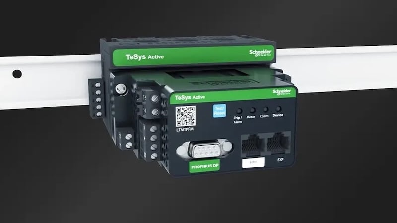
The next step is the addition of analog I/O. Our starter kit from Beckhoff includes a potentiometer and panel voltage display, in addition to the IPC and the digital I/O.
In many previous discussions about analog signals, we know that both voltage and current exist on the industry-standard spectrum, but voltage has the benefit of being a simpler property to manipulate from basic I/O devices. All systems, including those from Beckhoff, also provide modules for current I/O, should our system need them. The programming is almost always identical between the two methods.

Figure 1. The I/O rack contains one analog output (far right, EL4034 module) and an analog input (EL3255 module).
Installing the Analog Hardware
The potentiometer on this trainer is a fairly typical arrangement: three pins, with the center pin providing the sweeping voltage output signal from 0-10 volts. The two remaining pins on the connector will be attached to +10 volts and 0 volts.
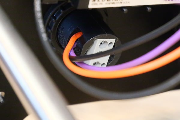
Figure 2. Three pins on the potentiometer. In this setup, orange = 10 v, purple = signal (center), and black = 0 v.
The analog output module is connected to a digital panel meter that displays +/- voltage for our convenience of testing programs. In the real world, however, the destination of this signal might be the speed of a motor drive or the position of a proportional fluid valve.
Defining the Code for Analog Read and Write
In a line of code almost identical to the previous digital example, our first project will simply pass along the potentiometer’s voltage value right to the analog output terminal, passing it through the analog and digital conversions inside the IPC
Our line of code is simple and familiar:
Your_AnlgOutput_Name := Your_AnlgInput_Name;
Both modules use integer data types and will yield a value from 0-32767, which correlates to 0-10 volts. Loading this code should produce a readout on the panel meter as if the voltage of the potentiometer was directly passed along.
Reversing the Sweep Direction
At this point, we may encounter a problem with the sweeping, as hinted earlier. As you turn the potentiometer from 0 to 10, you may see the voltage on the display actually decrease from 10 to 0, the exact opposite of what you expected. This results from +10 v and the 0 v wires being reversed on the potentiometer. The simple hardware solution is to remove power and reverse the wires on terminals 1 and 3.
However, with the power of the IPC, we can reverse the data another way. This might actually be intentional in some cases; for example, an analog distance sensor may be designed to prevent a rear-end vehicle collision. When the value of the sensor goes down, the power to the motors should increase.
A math formula can be implemented in the previous line of code that will invert the slope of the voltage change between the input and the output.
Your_AnlgOutput_Name := 32767-Your_AnlgInput_Name;
Remember, after a code change, select the “Login” button and “Login with online change” to install the new code revisions.
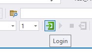
Figure 3. Remember to log in with online changes after each revision.
More About Integers (INTs)
You may have noticed that we didn’t use the full range of a 16-bit number in the previous code. A typical 16-bit integer would yield values from 0 to 65535 (which is 2^16-1). Since many industrial voltage scales swing from -10 to +10, our integer value must allow both positive and negative values; in other words, this is a signed integer.
Using this potentiometer as an input, we are limited to the input range of 0-10 volts. But what if we needed an output signal ranging from -10 to +10 as we turn the potentiometer?
In math terms, this means that we need to convert the input of 0 to 32767 into an output of -32767 to +32,767. First, we must double the input value to reach our intended output range.
Your_AnlgOutput_Name := 2*Your_AnlgInput_Name;
However, if we leave the solution at this step, we will exceed the signed integer value, and building the solution will yield an error and fail to download. To bring it back down to a signed integer level, subtract 32767 from the previous formula:
Your_AnlgOutput_Name := (2*Your_AnlgInput_Name)-32767;
With this formula, when our input potentiometer is at 0, the output will be -32767. However, when the potentiometer is increased to the maximum of 32767, the output value will still be 32767. Centering the potentiometer will provide a 0.0 volt output.

Figure 4. The potentiometer, a bit below its center position, yields a negative output voltage with the final revised code above.
Status Indicator Using If Statements and Comparisons
Variable values give us a great opportunity to explore operations beyond simple on/off results. For example, you can’t use a discrete sensor or a button to provide varying levels of input quantity; it’s simply ON or OFF.
Using our potentiometer, we could imagine it being a temperature sensor, a tank fill level, or a pressure sensor. If the value is below a certain threshold, our process works well. If it exceeds that threshold, we should consider a warning. If it gets much higher, the warning is more severe and should show a red alarm.
We’ll use “If statements” to build this logic; numerous ways exist to get the job done. We’ll only explore two.
Multiple If Statements
Our first example will follow a very common programming pattern. We will compare the potentiometer value to several threshold values that correlate to “safe,” “warning,” and “emergency” levels. Since the integer goes from 0-32767, we’ll arbitrarily say anything between 2,000 and 20,000 is a safe level, anything from 20,000 to 25,000 should be a warning, and above 25,000 is an emergency.
In our first statement, we state the interval for the “safe” level and turn on the green light while turning off any other colored lights:
IF V_Potentimeter >= 2000 AND V_Potentimeter < 20000 THEN
    V_Green_Light := TRUE;
    V_Yellow_Light := FALSE;
    V_Red_Light := FALSE;
END_IF
Simply repeat the above copy for the other two intervals, enabling the yellow light first and then the red light for the appropriate intervals.
As a final statement, if the value is below 2000, we want to set all lights to FALSE:
IF V_Potentimeter < 2000 THEN
    V_Green_Light := FALSE;
    V_Yellow_Light := FALSE;
    V_Red_Light := FALSE;
END_IF

Figure 5. Four If statements provide logic for each of the three indicator lights. Here, you can see the online value of each variable when logged in to the controller.
A benefit of using multiple if statements is that we can test each interval separately from all others. Also, the intervals may overlap since each expression is evaluated, regardless of whether the others are true. Still, we must be careful not to provide conflicting TRUE/FALSE output values to the lights if two statements should evaluate “TRUE” at the same time. This is known as a “destructive bit reference” in some settings. The result of multiple write commands to a single output will be determined by the scan cycle of the PLC. Whichever line is the final line evaluated for each output, that result will be implemented to the output terminals.
One If/Else Statement
We can re-create this same process inside a single statement with several possible options. The code is more condensed, but we cannot test each warning light separately as the entire code must be built properly before compiling. Also, if two of the IF/ELSIF condition lines should happen to be true, the code will only execute the first one, so this is not exactly identical to the previous example.
The code begins in the same manner as before, but instead of ending the IF statement immediately, we insert the next evaluation with an ELSIF (note the spelling here!)
IF V_Potentimeter >= 2000 AND V_Potentimeter < 20000 THEN
    V_Green_Light := TRUE;
    V_Yellow_Light := FALSE;
    V_Red_Light := FALSE;
ELSIF V_Potentimeter >= 20000 AND V_Potentimeter < 25000 THEN
    V_Green_Light := FALSE;
    V_Yellow_Light := TRUE;
    V_Red_Light := FALSE;
END_IF
Just add a new ELSIF condition to turn on the red light if the value is above 25000. The final statement of disabling all lights can be a final ELSE statement before the END_IF:
ELSE
    V_Green_Light := FALSE;
    V_Yellow_Light := FALSE;
    V_Red_Light := FALSE;<
END_IF
You don’t need a condition on the ELSE statement. If the other conditions are false, whatever is left, regardless of the value, must be true.

Figure 6. Multiple conditions combined into one If/Else statement.
These are only two examples of how to accomplish this task; several others exist.
Next Steps: Timing and Counting
In typical PLC logic, IEC timers and counters are essential tools in the programming kit. Structured text (ST) must provide similar functions, which will be explored in the next article.


Thank you for all the time and effort of article’s you have written sir they are great in explaining the subject and help newbies like me. I love reading your articles.