Facebook
 Google
 GitHub
 Linkedin
Tutorial: RSLogix For SLC and MicroLogix PLCs
Many PLC systems still require knowledge of the previous generation of RSLogix software from Rockwell, including the SLC 500 and the Lite software version for the MicroLogix family.
PLCs evolve much more slowly than most other computer systems. The primary reasons include the cost and risk of unnecessary upgrades. In other words, if it’s working properly, why should I spend the money to install something that I have never used before?
For these reasons, many users face aging technology that still works perfectly at the hardware level but requires some detective skills to dig up the correct software and adapters to solve programming challenges.
Today we will examine RSLogix 500 through the lens of the free ‘Lite’ version, designed for the MicroLogix 1000 PLC family. This small PLC is found in many schools and workbench environments and is how many engineers were initially introduced to PLCs.
Downloading and Installing RS Micro Starter Lite for MicroLogix 1000
Although free, this software can be tricky to locate. It was discontinued around 2017, yet support still exists.
As of this writing (Nov 2024), the software is available from Rockwell’s Compatibility/Download Center for account holders. Make an account or log in if you are already registered. As shown in Figure 1, type ‘1763’ into the search bar to find the MicroLogix 1100 series.
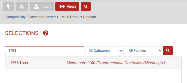
Figure 1. Rockwell software download center.
The MicroLogix 1100 series is programmed with the RS Micro Lite Software. The software is not available as an option for the most recent firmware revisions, so choose the 10.000 version (Figure 2) and proceed to downloads (Figure 3).

Figure 2. Select software version 10.000.

Figure 3. Select the software download option.
You will need to select files (Figure 4) and request the software be unlocked (Figure 5).
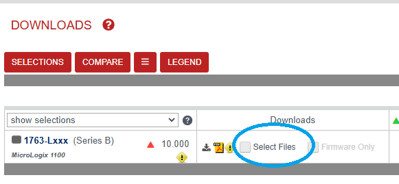
Figure 4. Select files for download.
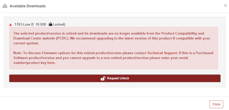
Figure 5. Request a software unlock.
In the Unlock Request pop-up, enter your email and the details for your unlock request (Figure 6). This is not a difficult process; simply provide a brief reason for your request. My reason is quite simple: I have a PLC that cannot be programmed in the most recent software IDEs.
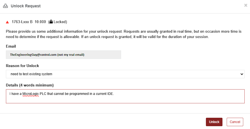
Figure 6. Justify your request for access to the software.
You should now have access. Next, you will need to install the RSLogix Micro Starter Lite and, maybe, RSLinx Classic Lite (Figure 7). If you have a current installation of other Rockwell software, you might have RSLinx Classic already installed. If so, you only need the Micro Starter Lite.
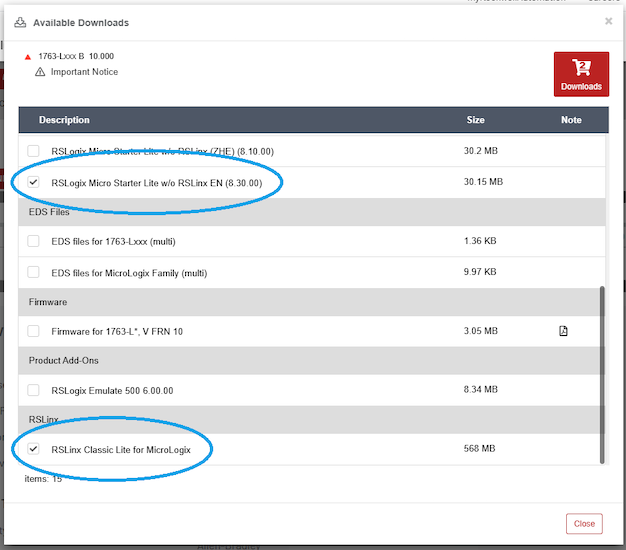
Figure 7. Select the software for both programming (required) and connection (optional).
Once these are downloaded and installed (you can use the Rockwell Download Manager or direct download process), you’re all set to program a MicroLogix 1000/1100 PLC.
MicroLogix vs. SLC vs. CompactLogix PLCs
This tutorial will focus on the MicroLogix 1000, one of the more basic PLCs in the entire Allen-Bradley (Rockwell) catalog. The overall process will be quite similar for an SLC 500 PLC, but there may be some differences depending on your network and CPU setup.
The programming environment will, likewise, be similar but not identical between the RS Micro Starter Lite and RSLogix 500. If you use a CompactLogix or ControlLogix PLC, this tutorial will not work; you should use these how-to guides instead (find the first one here).
However, one of the best things about Micro Starter Lite software is that you can obtain it and begin practicing programming for free.
Configuring the PLC Connection: RSLinx
If you have a MicroLogix 1000, you will need a programming cable: 1761-CBL-PM02, which can be found with either a serial or USB connection. For a typical laptop, the USB version is best.
Connect the PLC to the computer and apply power to the PLC. Before programming, we’ll need to connect with RSLinx, so open that application from the start menu: RSLinx Classic.
Go to the menu Communication -> Configure Drivers
We will need to add a new driver for this USB connection, and it’s in the drop-down menu as: “RS-232 DF1 devices”. Select this option and “Add New’. You simply need to choose the proper COM port from your device manager and Auto-Configure the connection (Figure 8). If the PLC is powered on, the auto-configuration should be successful.
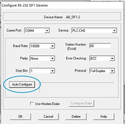
Figure 8. Configuring the RSLinx connection on COM4.
Connecting to the PLC: RS Micro Lite
Open RSLogix Micro from the Start menu. Before creating a program, we’ll connect to the PLC and upload the current program (if any exists).
With the software open, go to the top menu Comms -> Who Active Go Online and expand the AB_DF1-1 item. You should see the icon of a small MicroLogix PLC. Click to select this PLC (not the icon of the computer, that’s your programming workstation), and click OK. The software will ask you to create a new file and will then populate the IDE with the program that is currently running in the PLC.
If this PLC is in service, DO NOT download any new program. If this is a benchtop model and no longer used in service, you can safely erase or overwrite the current program.
Designing a Simple Ladder Logic Program
For this tutorial, we will simply allow a pushbutton to energize an output relay, in typical fashion for a PLC ‘hello world’ program.
But First, a Word on I/O Addressing
For those familiar with tag-based PLC memory, the strategy for the SLC/MicoLogix environment can be tricky.
We must first understand that all tags are already created in the PLC from the moment we open the program. This is good in the sense of simplicity. Need a timer? There’s already a set of timers ready to use.
But it can also be a problem in that memory is not free to use where you need it most. Maybe you need a bunch of counters but not many timers? You might not have enough space. But for this simple project, we’ll have plenty of room!
On the left sidebar tree, expand the folder called “Data Files.” You will see a list containing an Output file, Input file, as well as Staus, Binary, Timer, Counter, and others. Integer is another important one. Note that for this PLC, we only have 16-bit integers. Larger PLCs can use double integers (DINT) and float data types, among others.
Examine the Input file first as shown in Figure 9.

Figure 9. Examining the input file.
When expanded, you’ll see only a couple of rows. If you connect to a larger SLC 500 with many I/O modules, you’ll find more rows. My PLC has only 10 inputs, so I can only use inputs I:0/0 through I:0/9. Adding symbols and descriptions can be very useful in the ladder logic interface.
Now check out the Timer file (Figure 10). These timers have a base in 100ths of a second (pay attention there, it’s NOT milliseconds!).

Figure 10. Opening up the Timer file.
To use a timer in the ladder, we would call up T4:0 through T4:39. Then in later logic, we could use each timer’s bits, like T4:0/EN or T4:0/DN, or even T4:0/TT.
We’ll examine these timers in a later tutorial.
Simple Ladder Diagram
Our program must have one main routine, a ladder diagram in which the continuous logic scanning takes place. If you need smaller sub-routines, those can be accessed anytime, but you must design the main program within the main routine.
For our project, because of its small length, we’ll work exclusively in the main routine.
On the left sidebar, click on the MAIN ladder in the program files (Figure 11).

Figure 11. Accessing the MAIN ladder diagram.
If you are in REMOTE RUN mode (green color) as shown in Figure 12, then you’ll need to switch to PROGRAM mode (blue) or go offline to edit the program.
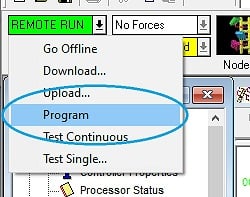
Figure 12. PROGRAM mode for editing the ladder diagram.
Drag in one new rung.
Click on the Examine if Closed (XIC) command and drag it to the left side of the rung until the box lights up green. Type in the address of the first input terminal: I:0/0.
Similarly, drag a momentary Output Energize coil (OTE) to the right side of the run. Use the very first address in the output file: O:0/0, as shown in Figure 13
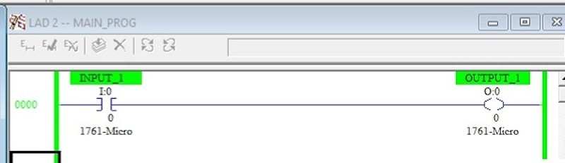
Figure 13. The final PLC program in RUN mode.
To download this program, go to the online menu and select ‘Download.’ If you are not prompted to go to RUN mode, select the online menu and choose RUN.
Testing the PLC
Our hardware setup for this very simple program will only involve a few wires.
Use one wire from the DC COM port for the first terminal bank and connect this to the ground of the DC power supply (Figure 14). Then, connect 24 V DC through a pushbutton and on to the first input terminal, marked I/0 on the PLC.
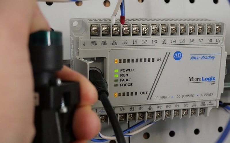
Figure 14. Testing our PLC program: depressing the push-button turns on the amber LEDs.
When the button is pressed, the amber LED for input terminal IN 0 should light up, as well as the output terminal OUT 0.
Next Up: Timers
In our next RSLogix tutorial, we’ll cover the use of timers and counters for the T4 and C5 data files in RSLogix and Micro Lite.
All images used courtesy of the author.
Related Content