Facebook
 Google
 GitHub
 Linkedin
Using FANUC’s EGD Protocol for Robot-to-Robot Communication
Handshaking between robots can be handled in many ways, one of them being GE-FANUC’s protocol called “Ethernet Global Data,” or EGD. Learn how to set up EGD on a pair of FANUC robots.
In any modern automated manufacturing setup, we need quick and seamless communication between every system. FANUC, being a leader in industrial robotics, offers various communication protocols, with Ethernet Global Data (or EGD) being a somewhat unique standout among a mix of industry-standard protocols.
This article provides a thorough explanation of EGD implementation, exploring applications of robot-to-robot communication, discussing the physical connections, IP address assignment, configuring EGD producer and consumer exchanges, and, finally, assigning I/O to the proper rack.
Importance of Robot-to-Robot Communication
Robot-to-robot communication unlocks extended capabilities in manufacturing cells. Consider scenarios where multiple robots collaborate on a single workpiece or operate in close proximity. EGD's rapid data exchange allows for:
- Coordinated motion
- Shared workspaces and collision avoidance
- Load balancing and task distribution
- Process synchronization
The inherent speed and predictability of EGD, based on UDP multicast/unicast, make it well-suited for time-critical inter-robot communication needs.
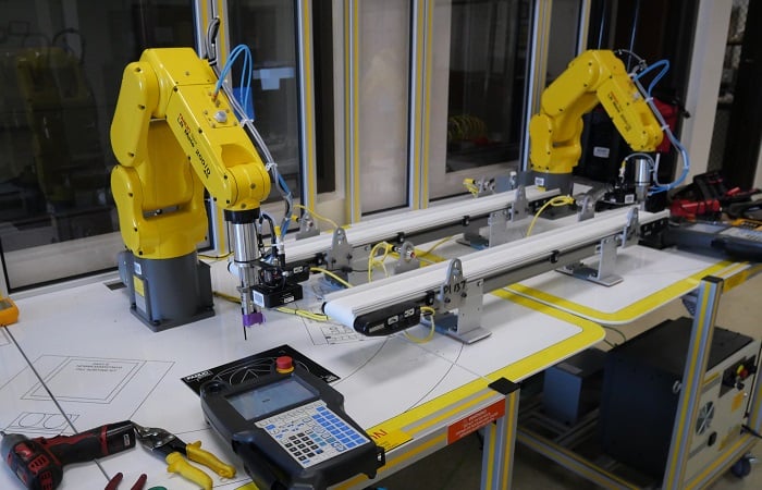
Figure 1. EGD is a popular option for communication between local FANUC robots. These robots are being used in an educational setting at San Joaquin Delta College in Stockton, CA.
To properly set up the EGD communication, we need to remember a few steps in the process. The exact procedure for each step may vary, as each robot contains different software options and configurations according to the original build sheet.
- Enable the EGD software option
- Connect the cables
- Configure the Ethernet port
- Set up the producer config
- Set up the consumer config
- Assign the proper I/O points to the EGD rack
Enabling the EGD Option in the Controller
First, ensure that the EGD (Ethernet Global Data) option is installed and enabled on both FANUC robot controllers (or more, if you intend to link more robots). This is a software option that needs to be purchased and enabled in the controller. It also depends on the Ethernet option being previously activated, but this is quite common for most robots in industry.
You can check for installed options through the teach pendant. Go to Menu -> I/O and, if it’s already enabled, you should see both EtherNet/IP and EGD I/O listed as options near the end. If not, you will need to contact FANUC to purchase the activation code(s).
Pay careful attention to the instructions for enabling the software during a controlled startup. Controllers may be corrupted during backups and installs, so I will not provide guidance on this process; it’s best to contact FANUC or an authorized local service directly to ensure you understand the proper steps for your controller.
Physical Connection for EGD
The physical layer of EGD communication in FANUC robot systems is a standard Ethernet network. This typically involves:
Ethernet Cables: Standard industrial Ethernet cables with RJ45 ends are all that is required. Shielded cables are recommended in noisy industrial environments to prevent electromagnetic interference.
Ethernet Ports: All Ethernet-enabled controllers have one or more RJ45 ports inside the cabinet door. In the example below, we show an R-30iB Mate controller. Be sure you know which connector aligns with the various port numbers for proper IP address assignment later.
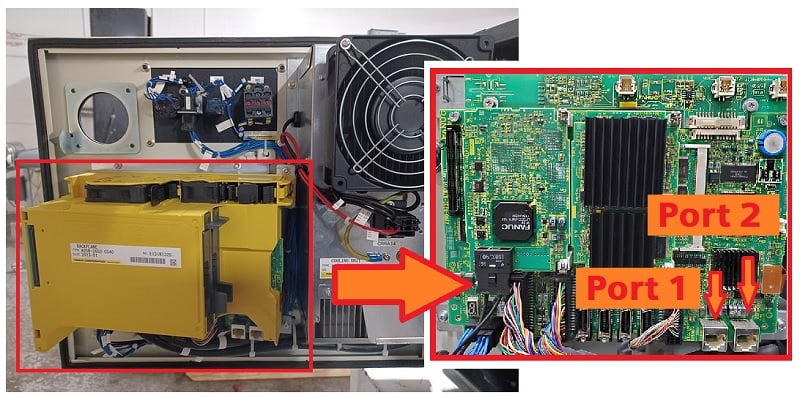
Figure 2. This R-30iB Mate controller has two ports, CD38A (Port 1) and CD38B (Port 2).
Industrial Ethernet Switch: If only two robots are linked, a single Ethernet cable will be sufficient. If three or more robots are involved, a switch will be necessary to link them all to the same network. Note: This is a local area network, not connected to the enterprise network.
It's also important to note that EGD uses a variation of the standard Ethernet protocol, so the data packets and their interpretation are proprietary to EGD. You cannot connect other Ethernet devices to this local network unless they are specially configured for EGD communication.
Network Configuration (IP Address)
Access the robot controller's network settings via the teach pendant (Menu -> Setup -> Host Comm -> TCP/IP). Configure the IP address, subnet mask, and default gateway for the Ethernet port that will be used for EGD communication. Ensure that the two robots are assigned different IP addresses on the same subnet.
From the TCP/IP config screen, you can select the function key port to toggle between physical ports 1 and 2, which are the left and right ports inside the controller door, respectively. Be sure you are configuring the port that actually has the cable connection to the other robot.
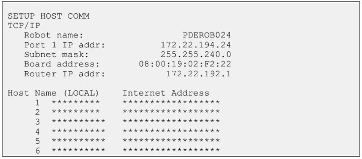
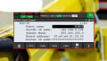
Figure 3. The IP address of each port can be set from the Host Comms menu.
EGD Producer and Consumer Configurations
EGD operates on a producer-consumer model. A producer robot publishes and sends data, and one or more consumer robots subscribe to and receive that data. The configuration process involves defining these roles and the data to be exchanged.
Navigate to the EGD setup screens, and both robots must have both roles configured for 2-way data exchange. This is typically found under Menu -> I/O -> EGD I/O (again, if this option is missing, contact FANUC to activate the software).
Producer Configuration
Host: Enter the IP address of the intended consumer robot.
ID: This is an ID that links the sending robot with the receiving robot. FANUC’s stated convention is to use an ID built from the last digit of the producer’s IP address, followed by the last digit of the consumer’s IP address.
For example, if robot 192.168.1.5 is sending data to robot 192.168.1.6, the ID would be 56.
The ID is limited to 99, so if either of the last octets exceeds 9, choose your own logical ID scheme.
Size: The number of bytes of the data block to be transmitted. EGD supports up to 1400 bytes of data per exchange. This data is mapped to specific I/O registers or memory locations within the robot controller.
Int: Set the interval at which the producer will send the data. This determines the refresh rate of the shared data and impacts network bandwidth. Usually, 100 ms is the default value.
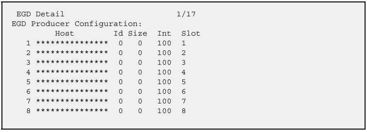
Figure 4. The producer configuration menu.
Consumer Configuration
To access the consumer configuration, press the arrow key down after entering the producer configuration(s) for all connections.
Unlike what we see in the producer configuration, there is no IP address because this robot is the consumer.
ID: Enter the exact exchange ID that the producer robot is broadcasting.
Size: The same number of bytes as will be sent from the producer.
Timeout: Trigger an alarm or error condition if a message is not received from the producer within a certain time. The recommended value is 3x the timeout value of the producer.
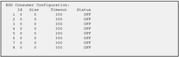
Figure 5. The consumer configuration menu.
I/O Assignments for Rack 88 (EGD)
FANUC robots use a rack-based I/O mapping system, and a specific rack number is designated for EGD I/O: rack 88. Other common racks include rack 48 for the physical I/O points on CRMA58/59, rack 89 for Ethernet, and others.
The process of assigning I/O to Rack 88 involves mapping internal robot registers or memory locations to EGD inputs and outputs.
1. Access I/O Configuration:
Navigate to Menu -> I/O -> Digital I/O, then press the function button Config.
2. Rack Assignment:
For EGD communication, the crucial step is to assign the Rack parameter to 88. This tells the robot controller that this I/O point will communicate via the EGD protocol.
3. Slot:
For EGD, the "slot" often refers to the specific EGD exchange or a logical grouping within the EGD configuration. While physical I/O cards have distinct slots, EGD's "slot" can be more abstract, defining which part of the EGD data block this I/O point corresponds to. It's often set to 1 for initial configurations unless multiple distinct EGD "logical" slots are being used.
4. Start Point:
Start Point: This defines the starting bit or word within the EGD data block for the assigned I/O. For example, if you are mapping a group of 16 digital inputs to EGD, your start point might be 1, and the next group of 16 could start at 17.
Example Scenario
Let's say Robot A (Producer) wants to send some digital output signals starting with DO[153] to Robot B (Consumer) to be matched as digital inputs starting at DI[153].
From the “EGO I/O” menu, we see that the communication is configured as two bytes of data (16 points), as per the producer and consumer “Data Size” fields.
Robot A (Producer)
Configure DO as follows:
Set a range of DO[153 - 160]; this will be the first byte.
Rack: 88
Slot: 1
Start: 1
Next, set a range of DO[161 - 168]; this will be the second byte.
Rack: 88
Slot: 1
Start: 9 (the first 8-bit byte was points 1-8)
Robot B (Consumer):
Configure DI as follows:
Set a range of DI[153 - 160]; this will be the first byte.
Rack: 88
Slot: 1
Start: 1
Next, set a range of DI[161 - 168]; this will be the second byte.
Rack: 88
Slot: 1
Start: 9
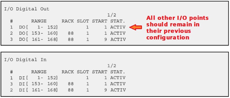
Figure 6. For this example, you would assign two ranges to the digital output assignment on the producer robot and the digital input assignment of the consumer robot. Best not to mess with the I/O assignments that already exist.
Simple Point-to-Point Communication
FANUC's Ethernet Global Data application provides a built-in method for high-speed, predictable data exchange between robots and other FANUC devices, and it’s easier to set up than any custom Ethernet messaging.
By understanding the rules and steps: proper cables and ports, setting up the IP address, configuring producer and consumer data, and correctly assigning I/O to Rack 88, it becomes much easier to tackle handshaking challenges without relying on custom setups or consuming physical I/O data points for an effective automation workcell.
All images used courtesy of the author