Facebook
 Google
 GitHub
 Linkedin
Validation and Verification in Finite Element Analysis (FEA)
Learn about the difference between FEA/FEM (Finite Element Methods/Finite Element Analysis), and look at a practical approach to verifying and validating.
While the terms verification and validation are often used interchangeably when discussing FEA/FEM (Finite Element Methods/Finite Element Analysis), they have very different meanings.
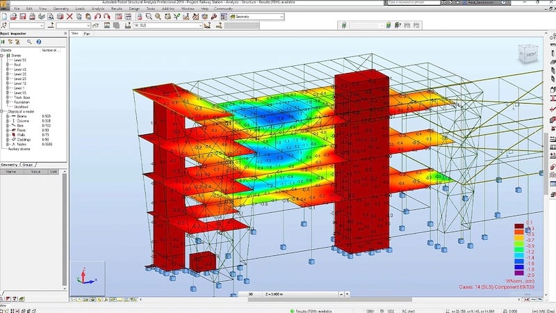
Analyzing the structural supports that factory automation interacts with often requires FEA to be verified and validated to ensure the model and results are accurate. Image courtesy of Autodesk.
Verification vs. Validation
The most succinct explanation of how verification and validation differ in finite element analysis is as follows: verification primarily focuses on the math and software implementation behind the finite element analysis, while validation looks at the model's accuracy.
Verification
Verification focuses on the mathematical aspects of FEA, determining if the solution that has been computed is accurate. And keep in mind that verification is critically important: if the mathematical model behind an FEA simulation is faulty, the results will be incorrect no matter how well the model represents the physical reality.
There are two distinct aspects to FEA verification: (1) that the theoretical solution has an acceptable level of error and (2) that the computer program that performs the FEA is working as expected. The second aspect is the responsibility of the software developers and programmers behind the FEA package that is being used. The first aspect, however, is a concern of the analyst performing the FEA simulation.
This leads to a very important question in the realm of FEA: how can you know how much error the analysis contains if you do not know what the correct results are? Is that not the purpose of a simulation: to find accurate answers for complex systems? This is where the field of error estimation comes into play.
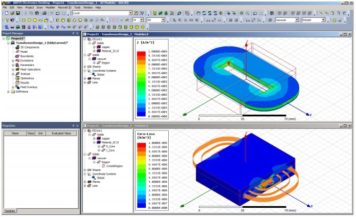
3D transformer simulations such as this one are performed in FEA packages that have been thoroughly verified before release. Image courtesy of ANSYS.
One of the keys to verification lies in convergence to a solution. Because FEA is so firmly grounded in mathematics, there are ways to determine at what rate the numerical solution will converge using what is known as a priori error estimation.
Error estimation can also be performed after a solution is complete, using a posteriori error estimation.
Keep in mind that this does not tell you how well the model represents physical reality but does tell you how much mathematical error is present in the model due to converting a continuous solution into a finite solution.
Validation
Validation is concerned with the accuracy of the model and looks at how well it captures the physical behavior of the real-world situation it is meant to simulate. Any model will be, even at its best, an approximation of the actual physical system.
In that context, validation focuses on the goal of the simulation and asks if the simulation meets the conditions for acceptance.
One of the tools used to evaluate computational models, including FEA models, is the validation pyramid.
In this process, the first step is to validate that the material is being modeled correctly by comparing it to the known behavior of a sample.
As one proceeds further up the pyramid, the model increases in its complexity. If at any point, the FEA simulation results do not coincide with the results of physical testing, then the model will be updated until the results are acceptable.
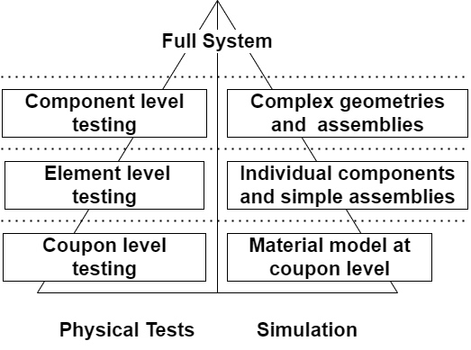
The validation pyramid.
Another way of looking at FEA model validation is, to begin with, a very simple model that you can confirm with basic calculations or laboratory tests.
As soon as the results at that level are correct, you increase the complexity. Never should an FEA simulation begin with the full system in all its complexity.
What Do You Need for Verification and Validation?
Although finite element analysis has been in use for many years, new elements, meshing algorithms, and numerical algorithms are constantly developing.
Earlier, we discussed a priori and a posteriori error estimates as key in FEA verification. In addition to those, FEA developers will also use simple problems with known solutions as tools to verify the mathematical portion of an FEA solution.
In solid mechanics, examples of simple problems include axial loads and basic cantilever beams; behavior around stress concentrations can also be evaluated to verify challenges in converging to a correct solution.
In short, error estimates and simple problems with known solutions are vital to verification.
For validation, the data from physical tests are ideal but may not always be possible. As mentioned earlier, beginning with simple loadings and boundary conditions with known solutions can be a great aid.

A single gear under analysis that will later be combined as part of a gear assembly. Image courtesy of Autodesk.
Also, keep in mind that models typically begin with very coarse meshes that are refined to minimize error and achieve convergence.
Convergence is also key to validation: if the solution does not converge, there is most likely an issue with (a) boundary conditions or constraints on the model, usually erring along the lines of not enough or incorrect application, (b) point loads used in place of distributed loads, or (c) too coarse a mesh in the area where convergence is failing to take place.
Example of Practical FEA Verification
When using commercial FEA packages such as those from Autodesk, Ansys, COMSOL, MSC Nastran, Opera, and others, the verification of both the numerical methods used and potential bugs in the program would affect the results that have already been performed.
Verification is primarily an issue when developing your own error estimators, elements, mesh generation, mesh refinement, or other code.
The ideal approach would be to compare the analysis results to known data or use basic models that represent problems with well-established solutions.
In solid mechanics, where the goal is to determine the deflection, stress, and strain of a 2D or 3D element, a first level test for verification of the FEA results would be an axially loaded element with one end constrained. The other end would be free, and a distributed load applied at the free end.
Closed-form solutions for this type of loading can be found in every undergraduate solid mechanic's textbook. If this simple model does not produce accurate results and there are no mistakes in the model, the problem lies with the FEA code and solution approach.
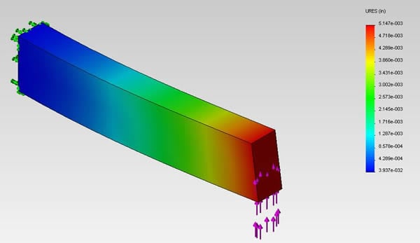
Cantilever beam fixed at one end with a transverse shear load applied at the free end. Image courtesy of Dassault SolidWorks.
The next phase of verification might include a simple beam deflection problem with one end constrained, the other end free, and a distributed load applied across the top of the beam. The beam will bend downward with a linear distribution of deflection, strain, and stress.
The deflection at the tip of the beam can easily be calculated, as can the maximum stress and where it should occur. As with axially loaded beams, such calculations can be found in every undergraduate level solid mechanics textbook.
More complex problems can then be addressed until the reliability and integrity of the FEA solutions and code have been established.
Example of Practical FEA Validation
During FEA analysis, the entire structure is not modeled at once, but individual components and subsystems are modeled and validated before the final structure is assembled. Even with those individual components, the analyst will begin with simplified loadings and boundary conditions to validate the performance of the model.
In fact, practical validation can be better understood as a repeating cycle rather than a linear process. If the model fails at any level in the validation pyramid, it must be modified, and inadequacies are addressed until an acceptable level of error is reached.
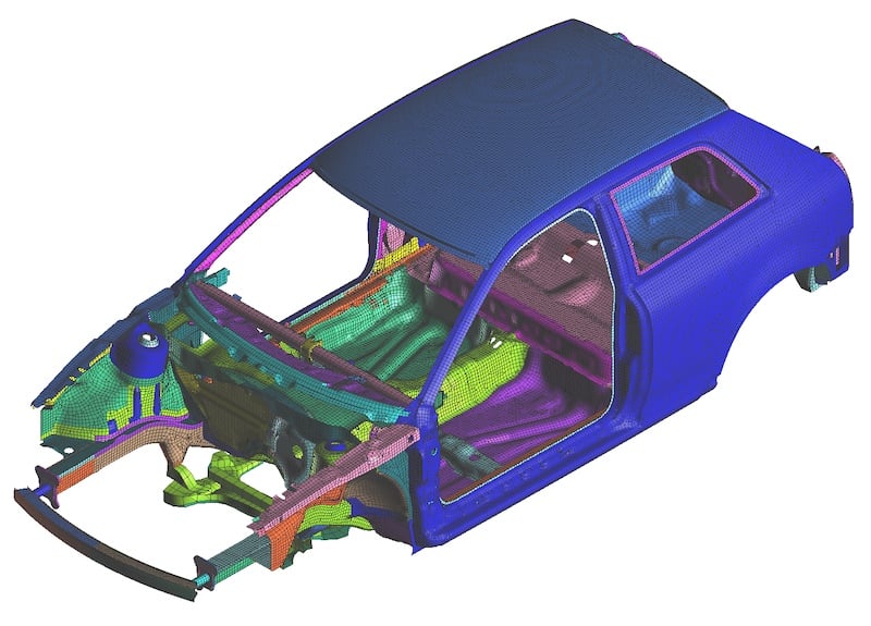
This FEA model would be a partial structure whose individual components had each been individually validated before assembly into a complete structure. Image courtesy of MSC Nastran.
As an example, consider how FEA analysis is performed on an automobile that includes components and structures made from aluminum, steel, polymers, and polymer composite materials.
While the behavior and material properties of aluminum and steel are already built into many FEA analysis programs, additional effort must be put into correctly setting up the composite materials because their behavior varies based on their orientation with respect to loadings. That is why the first level of the validation pyramid includes test coupons.
Once that is complete, individual components and simple assemblies, often consisting of basic structural elements such as the car chassis or the door frames, are modeled and validated.
Once validated, they are combined to form more complex assemblies (adding the composite door to the door frame and chassis, including the plastic bumper). Finally, the entire automobile is modeled and validated.
Verification focuses on the mathematical and coding aspects of FEA, while validation involves assessing the accuracy of the actual model.
Whether you are looking at the electromagnet/electromechanical interactions or just the solid mechanics' aspects of your design, you still need to validate your model in mind.