Facebook
 Google
 GitHub
 Linkedin
What is Finite Element Analysis?
This article provides an introduction to FEM/FEA and how it can be used in control systems and broader applications.
The Finite Element Method (FEM) is a numerical modeling tool whose practical use dates back to the 1940s. It was used in aeronautical and civil engineering.
Many believe that FEM contributed to Allied success in World War II as mechanical engineers used it to obtain faster, more extensive results for aircraft design. Despite the age of the original concepts behind FEM, its applicability and problem-solving power continue to grow. Finite Element Analysis support for microwave and RF engineers working with cutting edge technologies such as 5G.
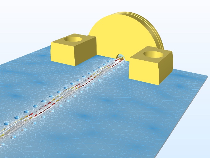
This image shows the mesh used to analyze the electric field norm for a grounded coplanar waveguide (GCPW) circuit with edge launch connectors. Image courtesy of COMSOL.
The rapid growth of computing power has enabled FEA, which is the practical application of FEM, to solve even more complex systems with speed and accuracy. Regardless of what area of engineering you may specialize in, it is useful to possess a basic understanding of how FEA works and what its possibilities are. The roots of FEA lie in the approximation of mechanical stress and strain.
Basic Concepts Behind FEM
Finite Element Method approximates a continuous system using a finite representation. In FEM, the continuous system is divided into a grid of discrete nodes that represent its geometry. The nodes are connected using elements that represent the behavior of the system between the nodes.
The result is a matrix of equations that can quickly grow large for problems with multiple degrees of freedom. This matrix can then be solved for the values at the nodes, which in turn feed into the elements to provide an approximation of the system’s behavior.
The grid of nodes is referred to as the mesh and correlates to the estimated error present in the model. Basically, the finer the mesh (i.e., the more nodes used), the better the model approximates the continuous system, and the less error will be present in the system.
A key part of FEA is generating an effective mesh. Image courtesy of ANSYS.
However, a balance must be achieved between the number of nodes present and the computational workload involved. For a 3 DOF (3 degrees of freedom) problem, each node contributes three variables to the system of equations that must be solved. Due to this, there are various methods for efficiently refining a mesh to obtain a low error estimate.
Nodes involve three things: conditions, loads, and equations representing the physical behavior at those nodes. Conditions are applied at the nodes, including boundary conditions, compatibility conditions (e.g., used when a node lies at the intersection of two different materials), and fundamental physics concepts such as equilibrium.
Some nodes will have loads applied to them, and (like conditions) the type of load corresponds to the modeling being performed. In addition, every node has one equation for every degree of freedom. In mechanical stress and strain models, it would simply be the force equilibrium equation.
As alluded to earlier, the elements approximate the system’s behavior between the nodes and (returning to a mechanical stress model) would provide information about the strain, the change in displacement relative to the node’s position. Strain depends heavily on two material properties: the modulus of elasticity of the material and its Poisson’s ratio.
From a purely mathematical viewpoint, the Finite Element Method is a way to solve ODEs (ordinary differential equations) and PDEs (partial differential equations). However, it only makes sense that a useful tool for science and engineering is closely tied to different equations.
Where FEA is Most Useful
FEA can be used to model very simple systems, but that defeats the purpose of having such a powerful tool available. It excels in modeling systems that are otherwise extremely challenging to model. This can include complex geometries, materials, domain changes and systems with non-linear characteristics, multiple materials, and the presence of mixed phenomena, such as thermoelectric analysis.
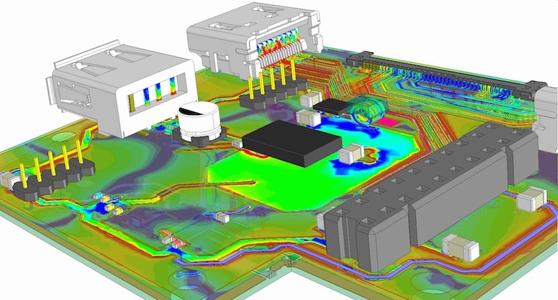
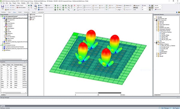
Results of electric field simulation related to a PCB using ANSYS. Image courtesy of ANSYS.
One of the strengths of FEA is the ability to reuse the same model to run multiple scenarios. This allows it to take the place of testing physical prototypes, which can be especially important when destructive testing is involved, or numerous physical tests can be expensive. FEA can also optimize the types of tests performed, as has been the case with some NASCAR wind tunnel testing, where it reduced the number of tests that needed to be run and the associated costs. It can also be leveraged to speed up the design process significantly.
Where FEA is Utilized
Finite element analysis can be used to model mechanical stress, vibration, diffusion, electrical conductivity, electromagnetism, heat transfer, and fluid flow. While many associate FEA/FEM with mechanical system modeling, it is used enough in connection with electromagnetics that there are entire books dedicated to the subject.
FEA has a variety of applications specific to control systems, as well. This includes modeling active vibration control systems, the design of control systems related to panel flutter suppression, and analysis of piezoelectric smart structures. Electrical engineers have used FEA for modeling semiconductor devices since the 1980s and power electronic systems, power electronics packaging, and synchronous permanent magnet motors.
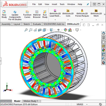
FEA packages such as Solidworks support magnetic and electromagnetic simulation for various applications, including the design of brushless DC electric motors. Image courtesy of SolidWorks.
FEA is being used to model various PCB materials to study how these materials will affect microwave and millimeter-wave circuits’ performance. Companies like TSMC use FEA tools to confirm the reliability of complete, integrated 2.5D and 3D silicon systems.
FEA has long been used to model the behavior of robotic arms, including soft robotic. You can also find FEA in the design of microrobots. These bots use phase-change actuators where nonlinear electrical conductivity and changing viscosity, density, and specific heat capacity all came into play.
As an analysis tool, FEA can speed up the industrial design process. With the widespread use of CAM (Computer-Aided Manufacturing) the same geometric model used to manufacture a part or component can also be used in the analysis.
FEM and FEA support the engineering design process by providing effective numerical simulation for many different applications and challenges in control systems. When used correctly, it can speed up the design process, reduce costs related to testing, and support optimized design.