 Facebook
 Google
 GitHub
 Linkedin
Electrical Pressure Elements
Several different technologies exist for the conversion of fluid pressure into an electrical signal response. These technologies form the basis of electronic pressure transmitters: devices designed to measure fluid pressure and transmit that information via electrical signals such as the 4-20 mA analog standard, or in digital form such as HART or FOUNDATION Fieldbus.
A brief survey of electronic pressure transmitters in contemporary use reveals a diverse representation of electrical pressure-sensing elements:
| Manufacturer | Model | Pressure sensor technology |
|---|---|---|
| ABB/Bailey | 2600T | Differential reluctance |
| ABB/Bailey | PTSD | Differential reluctance |
| ABB/Bailey | PTSP | Piezoresistive (strain gauge) |
| Foxboro | IDP10 | Piezoresistive (strain gauge) |
| Honeywell | ST3000 | Piezoresistive (strain gauge) |
| Rosemount | 1151 | Differential capacitance |
| Rosemount | 3051 | Differential capacitance |
| Rosemount | 3095 | Differential capacitance |
| Yokogawa | EJX series | Mechanical resonance |
Piezoresistive (strain gauge) sensors
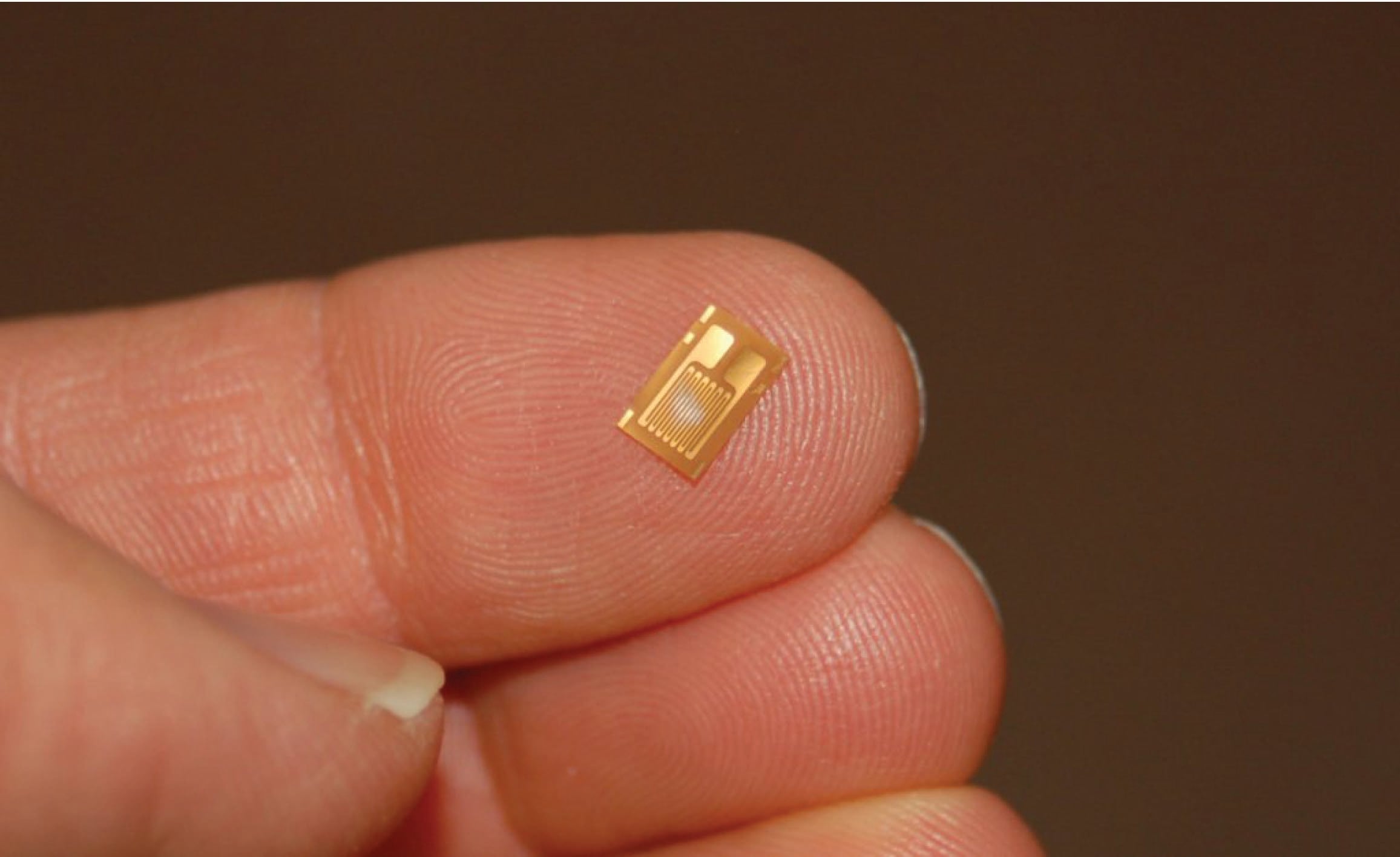
Piezoresistive means “pressure-sensitive resistance,” or a resistance that changes value with applied pressure. The strain gauge is a classic example of a piezoresistive element, a typical strain gauge element shown here on the tip of my finger:
In order to be practical, a strain gauge must be glued (bonded) on to a larger specimen capable of withstanding an applied force (stress):
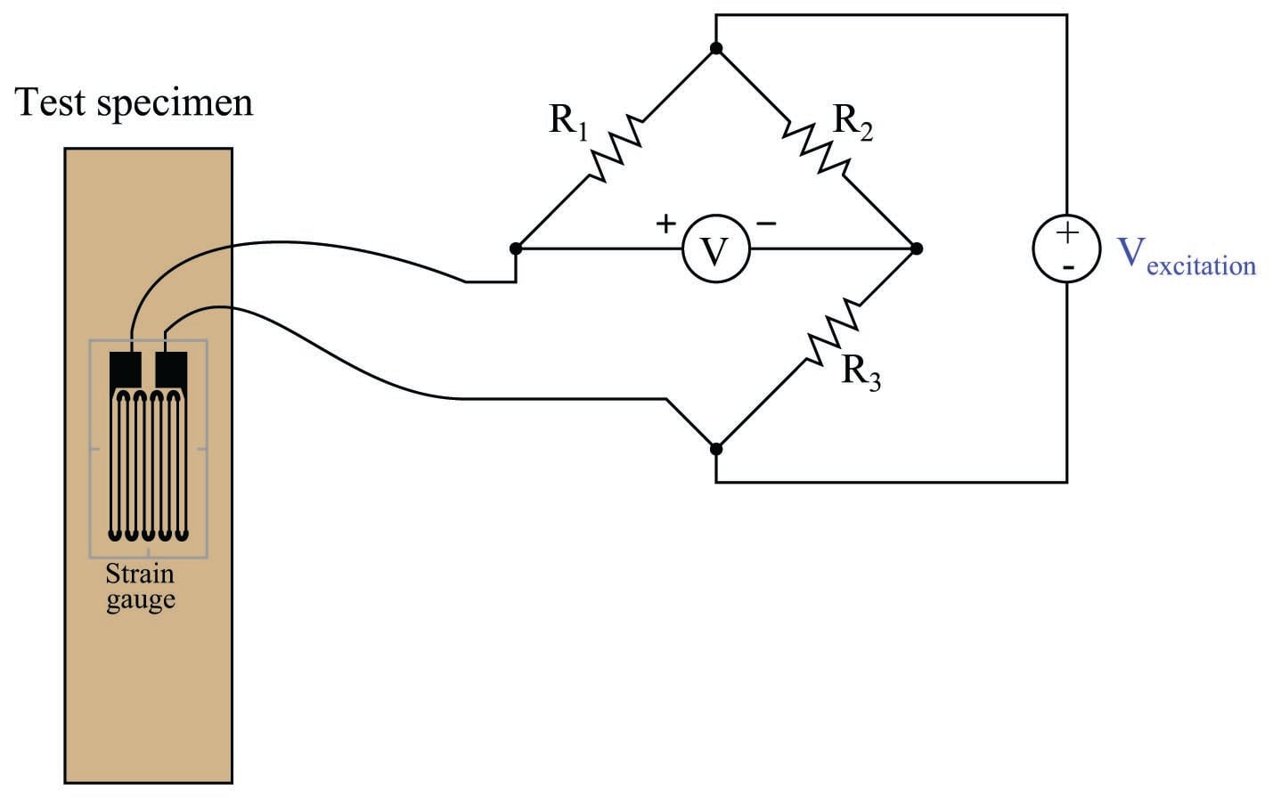
As the test specimen is stretched or compressed by the application of force, the conductors of the strain gauge are similarly deformed. Electrical resistance of any conductor is proportional to the ratio of length over cross-sectional area (\(R \propto {l \over A}\)), which means that tensile deformation (stretching) will increase electrical resistance by simultaneously increasing length and decreasing cross-sectional area while compressive deformation (squishing) will decrease electrical resistance by simultaneously decreasing length and increasing cross-sectional area.
Attaching a strain gauge to a diaphragm results in a device that changes resistance with applied pressure. Pressure forces the diaphragm to deform, which in turn causes the strain gauge to change resistance. By measuring this change in resistance, we can infer the amount of pressure applied to the diaphragm.
The classic strain gauge system represented in the previous illustration is made of metal (both the test specimen and the strain gauge itself). Within its elastic limits, many metals exhibit good spring characteristics. Metals, however, are subject to fatigue over repeated cycles of strain (tension and compression), and they will begin to “flow” if strained beyond their elastic limit. This is a common source of error in metallic piezoresistive pressure instruments: if overpressured, they tend to lose accuracy due to damage of the spring and strain gauge elements.
Modern manufacturing techniques have made possible the construction of strain gauges made of silicon instead of metal. Silicon exhibits very linear spring characteristics over its narrow range of motion, and a high resistance to fatigue. When a silicon strain gauge is over-stressed, it fails completely rather than “flows” as is the case with metal strain gauges. This is generally considered a better result, as it clearly indicates the need for sensor replacement (whereas a metallic strain sensor may give the false impression of continued function following an over-stress event).
Thus, most modern piezoresistive-based pressure instruments use silicon strain gauge elements to sense deformation of a diaphragm due to applied fluid pressure. A simplified illustration of a diaphragm / strain gauge pressure sensor is shown here:

As the diaphragm bows outward with applied fluid pressure, the strain gauge stretches to a greater length, causing its resistance to increase. This change in resistance imbalances the bridge circuit, causing a voltage (\(V_{out}\)) proportional to the amount of applied pressure. Thus, the strain gauge works to convert an applied pressure into a measurable voltage signal which may be amplified and converted into a 4-20 mA loop current signal (or into a digital “fieldbus” signal).
In some designs, a single silicon wafer serves as both the diaphragm and the strain gauge so as to fully exploit the excellent mechanical properties of silicon (high linearity and low fatigue). However, silicon is not chemically compatible with many process fluids, and so pressure must be transferred to the silicon diaphragm/sensor via a non-reactive fill fluid (commonly a silicone-based or fluorocarbon-based liquid). A metal isolating diaphragm transfers process fluid pressure to the fill fluid, which in turn transfers pressure to the silicon wafer. Another simplified illustration shows how this works:

The isolating diaphragm is designed to be much more flexible (less rigid) than the silicon diaphragm, because its purpose is to seamlessly transfer fluid pressure from the process fluid to the fill fluid, not to act as a spring element. In this way, the silicon sensor experiences the same pressure that it would if it were directly exposed to the process fluid, without having to contact the process fluid. The flexibility of the metal isolating diaphragm also means it experiences much less stress than the silicon sensing diaphragm, which avoiding the problems of metal fatigue experienced by transmitter designs using metal as the sensing (spring) element.
This use of a fill fluid to transfer pressure from an isolating diaphragm to a sensing diaphragm inside the transmitter is used in most if not all modern pressure transmitter designs, even those that are not piezoresistive.
An example of a pressure instrument utilizing a silicon strain gauge element is the Foxboro model IDP10 differential pressure transmitter, shown in the following photograph:

Differential capacitance sensors
Another common electrical pressure sensor design works on the principle of differential capacitance. In this design, the sensing element is a taut metal diaphragm located equidistant between two stationary metal surfaces, comprising three plates for a complementary pair of capacitors. An electrically insulating fill fluid (usually a liquid silicone compound) transfers motion from the isolating diaphragms to the sensing diaphragm, and also doubles as an effective dielectric for the two capacitors:

Any difference of pressure across the cell causes the diaphragm to flex in the direction of least pressure. The sensing diaphragm is a precision-manufactured spring element, meaning that its displacement is a predictable function of applied force. The applied force in this case can only be a function of differential pressure acting against the surface area of the diaphragm in accordance with the standard force-pressure-area equation \(F=PA\). In this case, we have two forces caused by two fluid pressures working against each other, so our force-pressure-area equation may be re-written to describe resultant force as a function of differential pressure (\(P_1 - P_2\)) and diaphragm area: \(F = (P_1 - P_2)A\). Since diaphragm area is constant, and force is predictably related to diaphragm displacement, all we need now in order to infer differential pressure is to accurately measure displacement of the diaphragm.
The diaphragm’s secondary function as one plate of two capacitors provides a convenient method for measuring displacement. Since capacitance between conductors is inversely proportional to the distance separating them, capacitance on the low-pressure side will increase while capacitance on the high-pressure side will decrease:

A capacitance detector circuit connected to this cell uses a high-frequency AC excitation signal to measure the different in capacitance between the two halves, translating that into a DC signal which ultimately becomes the signal output by the instrument representing pressure.
These pressure sensors are highly accurate, stable, and rugged. An interesting feature of this design – using two isolating diaphragms to transfer process fluid pressure to a single sensing diaphragm through an internal “fill fluid” – is that the solid frame bounds the motion of the two isolating diaphragms such that neither one is able to force the sensing diaphragm past its elastic limit. As the illustration shows, the higher-pressure isolating diaphragm gets pushed toward the metal frame, transferring its motion to the sensing diaphragm via the fill fluid. If too much pressure is applied to that side, the isolating diaphragm will merely “flatten” against the solid frame of the capsule and stop moving. This positively limits the isolating diaphragm’s motion so that it cannot possibly exert any more force on the sensing diaphragm, even if additional process fluid pressure is applied. This use of isolating diaphragms and fill fluid to transfer motion to the sensing diaphragm, employed in other styles of differential pressure sensor as well, gives modern differential pressure instruments excellent resistance to overpressure damage.
It should be noted that the use of a liquid fill fluid is key to this overpressure-resistant design. In order for the sensing diaphragm to accurately translate applied pressure into a proportional capacitance, it must not contact the conductive metal frame surrounding it. In order for any diaphragm to be protected against overpressure, however, it must contact a solid backstop to limit further travel. Thus, the need for non-contact (capacitance) and for contact (overpressure protection) are mutually exclusive, making it nearly impossible to perform both functions with a single sensing diaphragm. Using fill fluid to transfer pressure from isolating diaphragms to the sensing diaphragm allows us to separate the function of capacitive measurement (sensing diaphragm) from the function of overpressure protection (isolation diaphragms) so that each diaphragm may be optimized for a separate purpose.
A classic example of a pressure instrument based on the differential capacitance sensor is the Rosemount model 1151 differential pressure transmitter, shown in assembled form in the following photograph:

By removing four bolts from the transmitter, we are able to remove two flanges from the pressure capsule, exposing the isolating diaphragms to plain view:

A close-up photograph shows the construction of one of the isolating diaphragms, which unlike the sensing diaphragm is designed to be very flexible. The concentric corrugations in the metal of the diaphragm allow it to easily flex with applied pressure, transmitting process fluid pressure through the silicone fill fluid to the taut sensing diaphragm inside the differential capacitance cell:

The interior of the same differential capacitance sensor (revealed by cutting a Rosemount model 1151 sensor in half with a chop saw) shows the isolating diaphragms, the sensing diaphragm, and the ports connecting them together:

Here, the left-side isolating diaphragm is clearer to see than the right-side isolating diaphragm. A feature clearly evident in this photograph is the small clearance between the left-side isolating diaphragm and the internal metal frame, versus the spacious chamber in which the sensing diaphragm resides. Recall that these internal spaces are normally occupied by fill fluid, the purpose of which is to transfer pressure from the isolating diaphragms to the sensing diaphragm. As mentioned before, the solid metal frame limits the travel of each isolating diaphragm in such a way that the higher-pressure isolating diaphragm “bottoms out” on the metal frame before the sensing diaphragm can be pushed past its elastic limit. In this way, the sensing diaphragm is protected against damage from overpressure because the isolating diaphragms are simply not allowed to move any farther.
The differential capacitance sensor inherently measures differences in pressure applied between its two sides. In keeping with this functionality, this pressure instrument has two threaded ports into which fluid pressure may be applied. A later section in this chapter will elaborate on the utility of differential pressure transmitters (section 19.5 beginning on page ). All the electronic circuitry necessary for converting the sensor’s differential capacitance into an electronic signal representing pressure is housed in the blue-colored structure above the capsule and flanges.
A more modern realization of the differential capacitance pressure-sensing principle is the Rosemount model 3051 differential pressure transmitter:

As is the case with all differential pressure devices, this instrument has two ports through which fluid pressure may be applied to the sensor. The sensor, in turn, responds only to the difference in pressure between the ports.
The differential capacitance sensor construction is more complex in this particular pressure instrument, with the plane of the sensing diaphragm perpendicular to the plane of the two isolating diaphragms. This “coplanar” design is more compact than the older style of sensor, and more importantly it isolates the sensing diaphragm from flange bolt stress – one of the main sources of error in the previous design.

Take particular note of how the sensor assembly is not embedded in the solid metal frame as was the case with the original Rosemount design. Instead, the sensor assembly is relatively isolated from the frame, connected only by two capillary tubes joining it to the isolating diaphragms. This way, stresses inside the metal frame imparted by flange bolts have virtually no effect on the sensor.
A cutaway model of a Rosemount model 3051S (“supermodule”) DP transmitter shows how this all looks in real life:

Process fluid pressure applied to the isolating diaphragm(s) transfers to fill fluid inside the capillary tubes, conveying pressure to the taut diaphragm inside the differential capacitance sensor. Like the classic Rosemount model 1151 design, we see the fill fluid performing multiple functions:
- The fill fluid protects the delicate sensing diaphragm from contact with unclean or corrosive process fluids
- The fill fluid allows the isolating diaphragms to provide overpressure protection for the sensing diaphragm
- The fill fluid provides a medium of constant permittivity for the differential capacitance circuit to function
The “supermodule” series of Rosemount pressure transmitters shares the same coplanar design as the earlier 3051 models, but adds a new design feature: inclusion of the electronics within the stainless-steel module rather than the blue-painted upper housing. This feature allows the transmitter size to be significantly reduced if needed for applications with limited space.
Resonant element sensors
As any guitarist, violinist, or other stringed-instrument musician can tell you, the natural frequency of a tensed string increases with tension. This, in fact, is how stringed instruments are tuned: the tension on each string is precisely adjusted to achieve the desired resonant frequency.
Mathematically, the resonant frequency of a string may be described by the following formula:
\[f = {1 \over 2L} \sqrt{F_T \over \mu}\]
Where,
\(f\) = Fundamental resonant frequency of string (Hertz)
\(L\) = String length (meters)
\(F_T\) = String tension (newtons)
\(\mu\) = Unit mass of string (kilograms per meter)
It stands to reason, then, that a string may serve as a force sensor. All that is needed to complete the sensor is an oscillator circuit to keep the string vibrating at its resonant frequency, and that frequency becomes an indication of tension (force). If the force originates from pressure applied to some sensing element such as a bellows or diaphragm, the string’s resonant frequency will indicate fluid pressure. A proof-of-concept device based on this principle might look like this:

It should be noted that this principle of force measurement is nonlinear, as indicated by the equation for resonant frequency (tension force \(F\) lies inside the radicand). This means the pressure transmitter must be designed with an electronic characterizing function to “linearize” the frequency measurement into a pressure measurement.
The Foxboro company pioneered this concept in an early resonant wire design of pressure transmitter. Later, the Yokogawa corporation of Japan applied the concept using a pair of micro-machined silicon resonator structures bonded to a single sensing diaphragm, which became the basis for their successful line of “DPharp” pressure transmitters.
A photograph of a Yokogawa model EJA110 pressure transmitter with this technology is seen here:

Process pressure enters through ports in two flanges, presses against a pair of isolating diaphragms, transferring motion to a single sensing diaphragm via fill fluid where the resonant elements change frequency with diaphragm strain. Motion of the sensing diaphragm in either direction tenses one resonant element and compresses the other, causing their frequencies to deviate from each other. Electronic circuits within the upper housing measure the two resonant elements’ frequencies and generate an output signal proportional to their frequency difference. This, of course, is a representation of applied differential pressure.
Even when disassembled, the transmitter does not look much different from the more common differential capacitance sensor design.

The important design differences are hidden from view, inside the sensing capsule. Functionally, though, this transmitter is much the same as its differential-capacitance and piezoresistive cousins. This design even uses fill fluid to protect the delicate silicon resonators from potentially destructive process fluids, just like differential capacitance sensors and most piezoresistive sensor designs.
An interesting advantage of the resonant element pressure sensor is that the sensor signal is easily digitized. The vibration of each resonant element is sensed by the electronics package as an AC frequency. This frequency signal is “counted” by a digital counter circuit over a given span of time and converted to a binary digital representation without any need for an analog-to-digital converter (ADC) circuit. Quartz crystal electronic oscillators are extremely precise, providing the stable frequency reference necessary for comparison in any frequency-based instrument.
In the Yokogawa “DPharp” design, the two resonant elements oscillate at a nominal frequency of approximately 90 kHz. As the sensing diaphragm deforms with applied differential pressure, one resonator experiences tension while the other experiences compression, causing the frequency of the former to shift up and the latter to shift down (as much as \(\pm\) 20 kHz). The signal conditioning electronics inside the transmitter measures this difference in resonator frequency to infer applied pressure.
Mechanical adaptations
Most modern electronic pressure sensors convert very small diaphragm motions into electrical signals through the use of sensitive motion-sensing techniques (strain gauge sensors, differential capacitance cells, etc.). Diaphragms made from elastic materials behave as springs, but circular diaphragms exhibit very nonlinear behavior when significantly stretched unlike classic spring designs such as coil and leaf springs which exhibit linear behavior over a wide range of motion. Therefore, in order to yield a linear response to pressure, a diaphragm-based pressure sensor must be designed in such a way that the diaphragm stretches very little over the normal range of operation. Limiting the displacement of a diaphragm necessitates highly sensitive motion-detection techniques such as strain gauge sensors, differential capacitance cells, and mechanical resonance sensors to convert that diaphragm’s very slight motion into an electronic signal.
An alternative approach to electronic pressure measurement is to use mechanical pressure-sensing elements with more linear pressure-displacement characteristics – such as bourdon tubes and spring-loaded bellows – and then detect the large-scale motion of the pressure element using a less-sophisticated electrical motion-sensing device such as a potentiometer, LVDT, or Hall Effect sensor. In other words, we take the sort of mechanism commonly found in a direct-reading pressure gauge and attach it to a potentiometer (or similar device) to derive an electrical signal from the pressure measurement.
The following photographs show front and rear views of an electronic pressure transmitter using a large C-shaped bourdon tube as the sensing element (seen in the left-hand photograph):


This alternative approach is undeniably simpler and less expensive to manufacture than the more sophisticated approaches used with diaphragm-based pressure instruments, but is prone to greater inaccuracies. Even bourdon tubes and bellows are not perfectly linear spring elements, and the substantial motions involved with using such pressure elements introduces the possibility of hysteresis errors (where the instrument does not respond accurately during reversals of pressure, where the mechanism changes direction of motion) due to mechanism friction, and deadband errors due to backlash (looseness) in mechanical connections.
You are likely to encounter this sort of pressure instrument design in direct-reading gauges equipped with electronic transmitting capability. An instrument manufacturer will take a proven product line of pressure gauge and add a motion-sensing device to it that generates an electric signal proportional to mechanical movement inside the gauge, resulting in an inexpensive pressure transmitter that happens to double as a direct-reading pressure gauge.

Could you suggest some sensor supplier for transmitters?