 Facebook
 Google
 GitHub
 Linkedin
Pressure Sensor Accessories
Multiple accessories exist for pressure-sensing devices to function optimally in challenging process environments. Sometimes, we must use special accessories to protect the pressure instrument against hazards of certain process fluids. One such hazard is pressure pulsation, for example at the discharge of a piston-type (positive-displacement) high-pressure pump. Pulsating pressure can quickly damage mechanical sensors such as bourdon tubes, either by wear of the mechanism transferring pressure element motion to an indicating needle, and/or fatigue of the metal element itself.
Valve manifolds
An important accessory to the DP transmitter is the valve manifold. This device incorporates manual valves to isolate and equalize pressure from the process to the transmitter, for maintenance and calibration purposes.
The following illustration shows the three valves comprising a three-valve manifold (within the dotted-line box), as well as a fourth valve called a “bleed” valve used to vent trapped fluid pressure to atmosphere:
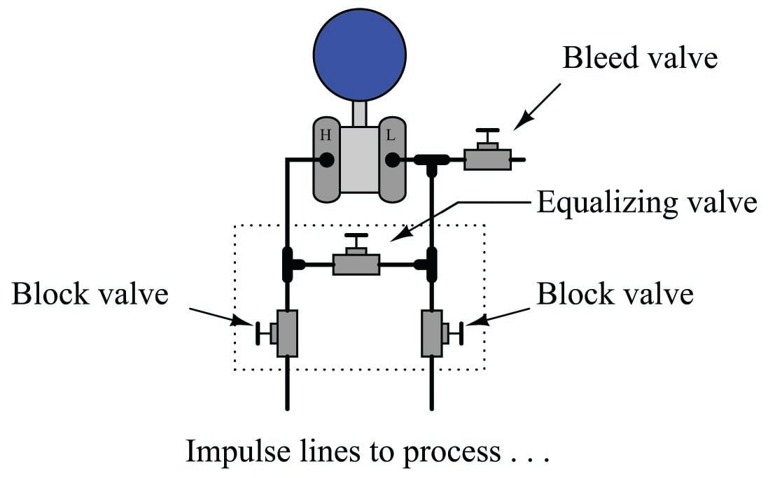
While this illustration shows the three valves as separate devices, connected together and to the transmitter by tubing, three-valve manifolds are more commonly manufactured as monolithic devices: the three valves cast together into one block of metal, attaching to the pressure transmitter by way of a flanged face with O-ring seals. Bleed valves are most commonly found as separate devices threaded into one or more of the ports on the transmitter’s diaphragm chambers.
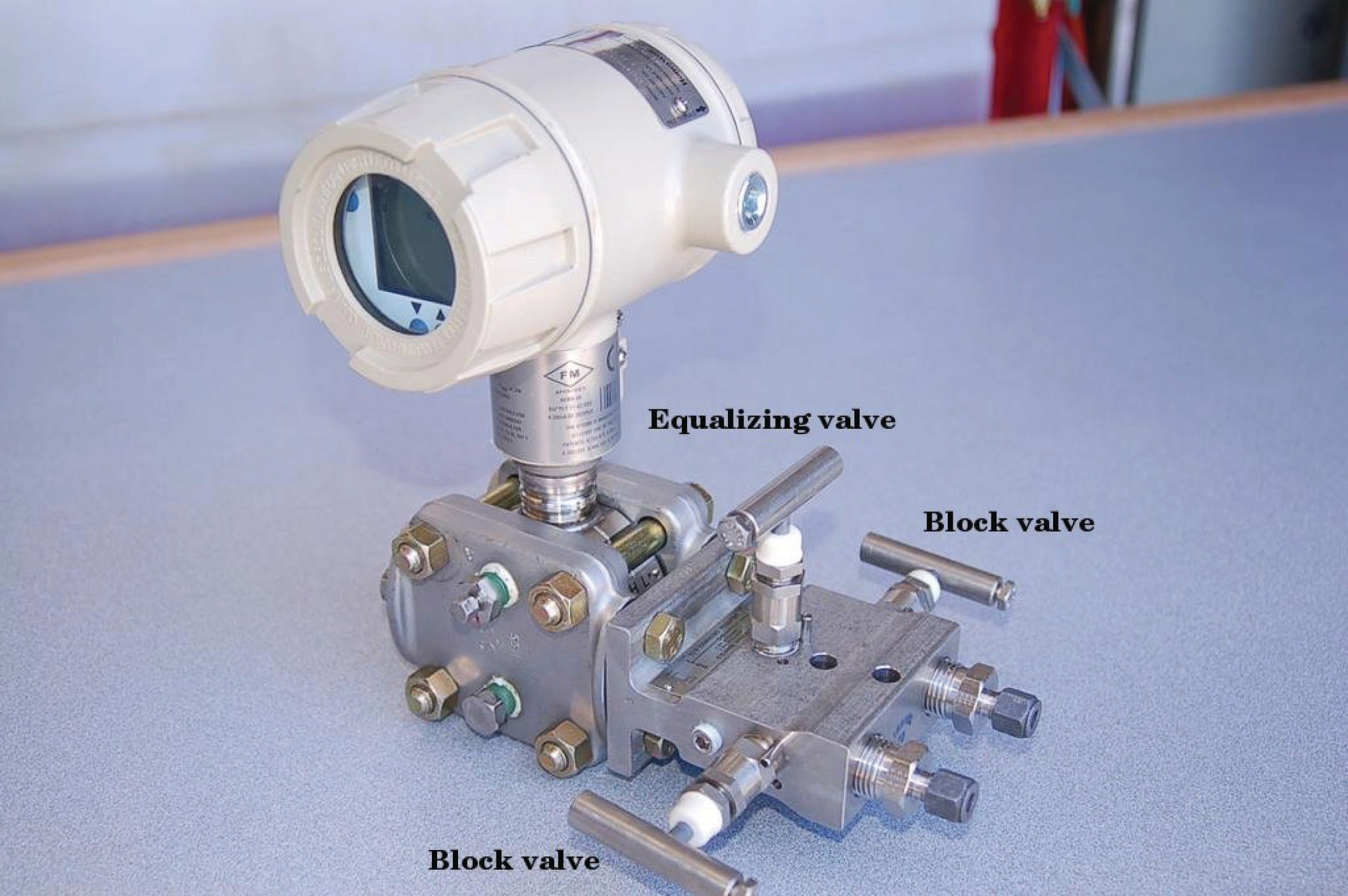
The following photograph shows a three-valve manifold bolted to a Honeywell model ST3000 differential pressure transmitter. A bleed valve fitting may be seen inserted into the upper port on the nearest diaphragm capsule flange:
In normal operation, the two block valves are left open to allow process fluid pressure to reach the transmitter. The equalizing valve is left tightly shut so no fluid can pass between the “high” and “low” pressure sides. To isolate the transmitter from the process for maintenance, one must close the block valves and open the equalizing valve. The best sequence to follow is to first close the high-pressure block valve, then open the equalizing valve, then close the low-pressure block valve. This sequence ensures the transmitter cannot be exposed to a high differential pressure during the isolation procedure, and that the trapped fluid pressure inside the transmitter will be as low as possible prior to “venting” to atmosphere. Finally, the “bleed” valve is opened at the very last step to relieve pent-up fluid pressure within the manifold and transmitter chambers:
Final valve positions for both states are shown in the following illustrations:

For added safety, shut block valves should be tagged (and possibly locked) so that no unauthorized people will open them up in a state when the transmitter is vented or removed from the manifold. In other words, the same safety procedure of lock-out/tag-out (LOTO) common to electrical maintenance work is applicable to isolation valves as well.
A variation on this theme is the five-valve manifold, shown in this illustration:

The presence of a built-in bleed valve in the five-valve manifold allows the technician to vent trapped pressure through a tube to some remote location, rather than directly venting at the transmitter. Valve positions for normal operation and maintenance on this manifold are as follows:

It is critically important that the equalizing valve(s) never be open on any transmitter manifold while both block valves are open! Doing so will allow process fluid to flow through the equalizing valve(s) from the high-pressure side of the process to the low-pressure side of the process. If the impulse tubes connecting the manifold to the process are intentionally filled with a fill fluid (such as glycerin, to displace process water from entering the impulse tubes; or water in a steam system), this fill fluid will be lost. Also, if the process fluid is dangerously hot or radioactive, a combination of open equalizing and block valves will let that dangerous fluid reach the transmitter and manifold, possibly causing damage or creating a personal hazard. Speaking from personal experience, I once made this mistake on a DP transmitter connected to a steam system, causing hot steam to flow through the manifold and overheat the equalizing valve so that it seized open and could not be shut again! The only way I was able to stop the flow of hot steam through the manifold was to locate and shut a sliding-gate hand valve between the impulse tube and the process pipe. Fortunately, this cast steel valve was not damaged by the heat and was still able to shut off the flow.
Pressure transmitter valve manifolds also come in single block-and-bleed configurations, for gauge pressure applications. Here, the “low” pressure port of the transmitter is vented to atmosphere, with only the “high” pressure port connected to the impulse line:

The following photograph shows a bank of eight pressure transmitters, seven out of the eight being equipped with a single block-and-bleed manifold. The eighth transmitter (bottom row, second-from left) sports a 5-valve manifold:

If you look closely at the photograph, you can see the bleed valve fittings installed on all the upper ports. Only the transmitter with the 5-valve manifold has two bleed valve fittings because it is the only DP transmitter of the group. The other seven transmitters are all gauge pressure units, and so only have one port to bleed.
A good habit to cultivate when operating valve handles on transmitter manifolds is to “back off” the open valves approximately one-quarter turn after opening. This discourages seizing in the full-open position, and also makes it possible for someone to more easily tell the states of the valves by feel: a closed valve will not easily turn (because it is tightened onto its seat) while an open valve is free to turn either direction a bit. Since there should be no flow going through the valves of a transmitter manifold, it is irrelevant whether an open manifold valve is 100% open or 90% open or 80% open, so there is no harm in “backing off” an open valve from the full-open position. It would of course be bad to do this with a closed valve, since any valve plug must be pressed tight into its seat in order to achieve positive shut-off.
Bleed (vent) fittings
Before removing a pressure transmitter from live service, the technician must “bleed” or “vent” accumulated fluid pressure to atmosphere in order to achieve a zero energy state prior to disconnecting the transmitter from the impulse lines. Some valve manifolds provide a bleed valve for doing just this, but many do not. An inexpensive and common accessory for pressure-sensing instruments (especially transmitters) is the bleed valve fitting or vent valve fitting, installed on the instrument as a discrete device. The most common bleed fitting is equipped with 1/4 inch male NPT pipe threads, for installation into one of the 1/4 inch female NPT pipe ports typically provided on pressure transmitter flanges. The bleed fitting is operated with a small wrench, loosening a ball-tipped plug off its seat to allow process fluid to escape through a small vent hole in the side of the fitting. The following photographs show close-up views of a bleed fitting both assembled (left) and with the plug fully extracted from the fitting (right). The bleed hole may be clearly seen in both photographs:


When installed directly on the flanges of a pressure instrument, these bleed valves may be used to bleed unwanted fluids from the pressure chambers, for example bleeding air bubbles from an instrument intended to sense water pressure, or bleeding condensed water out of an instrument intended to sense compressed air pressure.
The following photographs show bleed fittings installed two different ways on the side of a pressure transmitter flange, one way to bleed gas out of a liquid process (located on top) and the other way to bleed liquid out of a gas process (located on bottom):


With the bleed plug completely removed, the open bleed fitting provides a port through which one may apply air pressure for testing the response of the pressure transmitter. A special test fitting called a bleed port adapter or DP transmitter calibration fitting – colloquially known as a stinger – threads into the opened bleed fitting. A photograph of a bleed port adapter is shown here:

This special fitting allows a compression-style tube to be temporarily connected to the opened bleed port, which then allows the connection of an air pump and test pressure gauge to the transmitter. Thus, the bleed port adapter enables a technician to conveniently apply test pressures to the DP transmitter without having to loosen any of the instrument manifold bolts, tapered thread pipe connections, or impulse tube compression fittings.
When performing field checks of pressure transmitters, bleed port adapters substantially reduce the amount of time necessary to field-test pressure instruments. The following sequence of illustrations show how a bleed port adapter may be used in conjunction with a three-valve instrument manifold to isolate a DP transmitter from a process and then subject it to test pressures from a hand pump:

Note how both bleed vents must be opened, and the equalizing valve shut, in order to apply a test pressure to the DP transmitter. Although it is possible to safely bleed pressure from both sides of a DP instrument through just one bleed fitting (through the open equalizing valve), both bleeds must be open in order to perform a pressure test. If the “L” side bleed fitting is left in the shut position, some pressure may be trapped there as pressure is applied to the “H” side by the hand pump. If the equalizing valve is left open, no difference of pressure will be allowed to form across the DP instrument.
Pressure pulsation damping
A simple way to mitigate the effects of pulsation on a pressure gauge is to fill the inside of the gauge with a viscous liquid such as glycerin or oil. The inherent friction of this fill liquid has a “shock-absorber” quality which damps the gauge mechanism’s oscillatory motion and helps protect against damage from pulsations or from external vibration. This method is ineffectual for high-amplitude pulsations, though.
An oil-filled pressure gauge may be seen in the following photograph. Note the air bubble near the top of the gauge face, which is the only visual indication of an oil filling:

A more sophisticated method for damping pulsations seen by a pressure instrument is called a snubber, and it consists of a fluid restriction placed between with the pressure sensor and the process. The simplest example of a snubber is a simple needle valve (an adjustable valve designed for low flow rates) placed in a mid-open position, restricting fluid flow in and out of a pressure gauge:

At first, the placement of a throttling valve between the process and a pressure-measuring instrument seems rather strange, because there should not be any continuous flow in or out of the gauge for such a valve to throttle! However, a pulsing pressure causes a small amount of alternating flow in and out of the pressure instrument, owing to the expansion and contraction of the mechanical pressure-sensing element (bellows, diaphragm, or bourdon tube). The needle valve provides a restriction for this flow which, when combined with the fluid capacitance of the pressure instrument, combine to form a low-pass filter of sorts. By impeding the flow of fluid in and out of the pressure instrument, that instrument is prevented from “seeing” the high and low peaks of the pulsating pressure. Instead, the instrument registers a much steadier pressure over time. An electrical analogy for a pressure snubber is an RC low-pass filter circuit “damping” voltage pulsations from reaching a DC voltmeter:

One potential problem with the needle valve solution is that the small orifice inside the needle valve may plug up over time with debris from dirty process fluid. This, of course, would be bad because plugging will cause the pressure instrument to respond too slowly, or not at all if the plugging is complete.
A solution to this problem is to fill the pressure sensor mechanism with a clean liquid (called a fill fluid) and use that fill fluid to transfer pressure from the process fluid to the pressure-sensing element using a slack diaphragm or some other membrane separating the process fluid from the fill fluid:

It should be noted that most pressure snubbers utilize a fixed-geometry orifice rather than an adjustable needle valve to dampen pressure pulsations seen at the pressure gauge.
In order for the fill fluid and isolating diaphragm to work effectively, there cannot be any gas bubbles in the fill fluid – it must be a “solid” hydraulic system from the diaphragm to the sensing element. Gas bubbles present in the filled system would make that volume compressible, which means the isolating diaphragm would have to move more than necessary to transfer pressure to the instrument’s sensing element. This would mean motion at the isolating diaphragm caused by process pressure changes would be “lost” and not fully transferred to the instrument’s sensing element, thereby introducing a pressure measurement error. For this reason, isolating diaphragm systems for pressure instruments are usually “packed” with fill fluid at the point and time of manufacture, then sealed in such a way that they cannot be opened for any form of maintenance. Consequently, any fill fluid leak in such a system immediately ruins it.
Remote and chemical seals
Isolating diaphragms have merit even in scenarios where pressure pulsations are not a problem. Consider the case of a food-processing system where we must remotely measure pressure inside a mixing vessel:

The presence of the tube connecting the vessel to the pressure gauge poses a hygiene problem. Stagnant process fluid (in this case, some liquid food product) inside the tube will encourage microbial growth, which will eventually contaminate the vessel no matter how well or how often the vessel is cleaned. Even automated Clean-In-Place and Steam-In-Place (CIP and SIP, respectively) protocols where the vessel is chemically purged between batches cannot prevent this problem because the cleaning agents never purge the entire length of the tubing (ultimately, to the bourdon tube or other sensing element inside the gauge).
A solution to this problem is to install an isolating diaphragm at the vessel, and a liquid-filled capillary tube to transfer sensed pressure to the instrument. Process pressure presses against this diaphragm, which in turn transfers pressure to the “fill fluid” inside the capillary tube. This sealed fill fluid then presses against the instrument’s sensing element (diaphragm, bourdon tube, bellows, etc.). Process (food) liquid cannot enter this sealed tube, and the isolating diaphragm will be cleaned with every CIP cycle. Thus, we completely eliminate the problem of microbial contamination:

Such systems are often referred to as remote seals, and they are available on a number of different pressure instruments including gauges, transmitters, and switches. If the purpose of an isolating diaphragm and fill fluid is to protect the sensitive instrument from corrosive or otherwise harsh chemicals, it is often referred to as a chemical seal.
The following photograph shows a pressure gauge equipped with a chemical seal diaphragm. Note that the chemical seal on this particular gauge is close-coupled to the gauge, since the only goal here is protection of the gauge from harsh process fluids, not the ability to remotely mount the gauge:
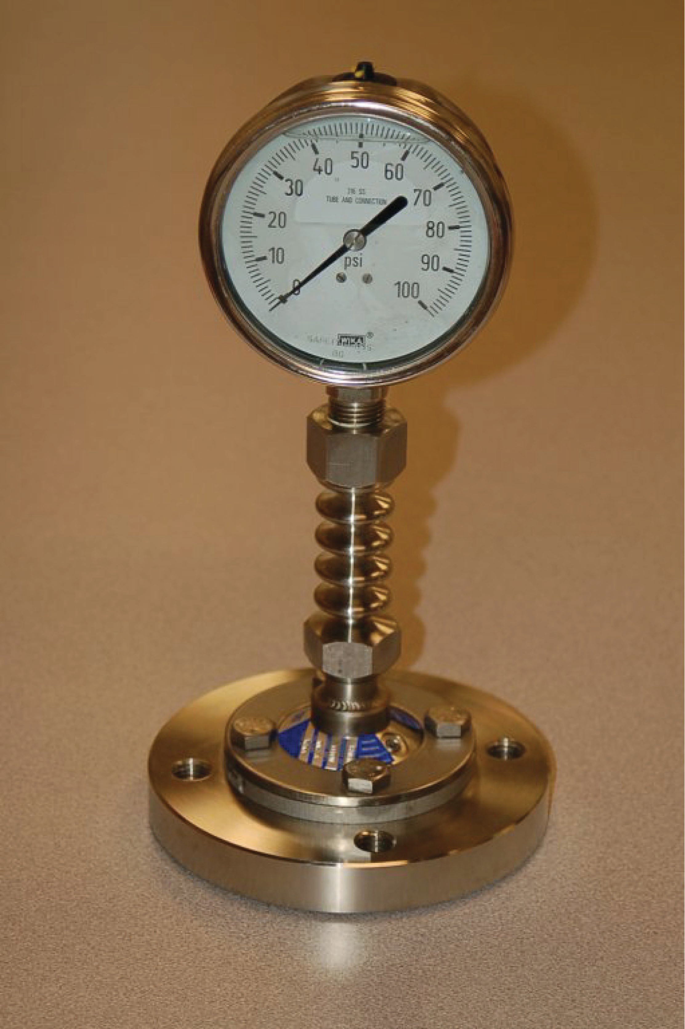
A view facing the bottom of the flange reveals the thin metal isolating diaphragm keeping process fluid from entering the gauge mechanism. Only inert fill fluid occupies the space between this diaphragm and the gauge’s bourdon tube:

The following illustration shows how the fill fluid transfers process fluid pressure to the gauge’s bourdon tube element while isolating that bourdon tube from the process fluid (shown here inside a pipe):

The only difference between this chemical-seal gauge and a remote-seal gauge is the small-diameter capillary tubing used to connect the gauge to a remote diaphragm. An illustration showing the internals of a remote seal system appears here:

Direct-reading gauges are not the only type of pressure instruments benefiting from remote seals. Pressure switches and pressure transmitters may also employ remote seals for the same reasons: protection of the transmitter sensor from harsh process fluid, elimination of impulse tube clogging problems, and/or the prevention of “dead-end” tube lengths where organic process fluid would stagnate and harbor microbial growths. In this photograph, you see three pressure sensing devices (gauge, transmitter, and switch, from top to bottom), each one with its own remote seal to sense fluid pressure in a large pipe:

The pressure transmitter (a Yokogawa unit) is the only instrument shown here using a capillary tube. The other two instruments use short lengths of rigid pipe. The capillary is visible in this photograph as a coiled tube covered in black plastic. It is actually a very small-diameter metal tube enclosed in a spiral-metal protective sheath which is in turn covered by black plastic.
This particular application happens to be in wastewater treatment, where sludge has a tendency to clog instrument impulse lines connected to the main piping. With remote seals in place, that problem is completely eliminated.
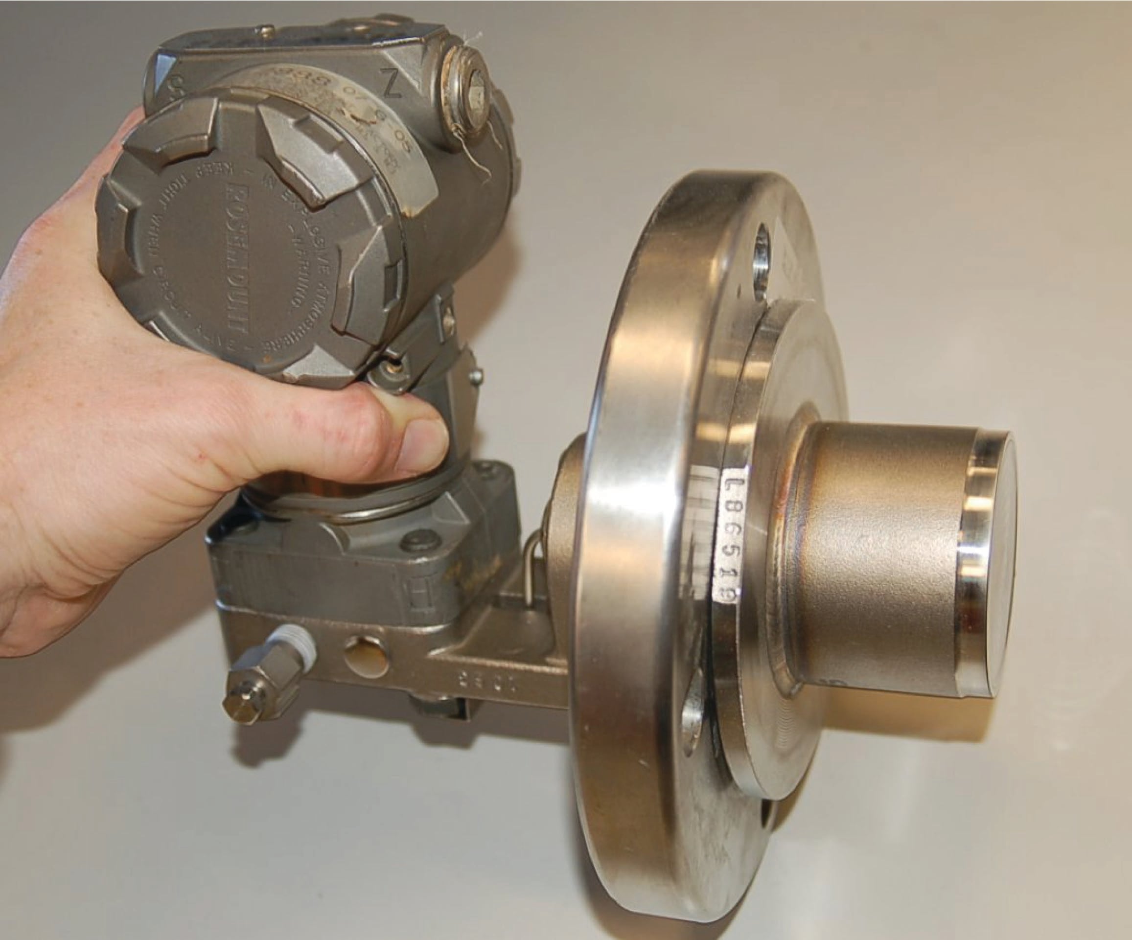
The following photograph shows a Rosemount model 1151 electronic pressure transmitter equipped with a remote sealing diaphragm. Here we may see the coiled metal (“armor”) sheath protecting the capillary tube from damage:

A close-up view of the sealing diaphragm shows its corrugated design, allowing the metal to easily flex and transfer pressure to the fill fluid within the capillary tubing:

As with the isolating diaphragms of the pressure-sensing capsule, these remote diaphragms need only transfer process fluid pressure to the fill fluid and (ultimately) to the taut sensing element inside the instrument. Therefore, these diaphragms perform their function best if they are designed to easily flex. This allows the sensing diaphragm to provide the vast majority of the opposing force to the fluid pressure, as though it were the only spring element in the fluid system.
The connection point between the capillary tube and the transmitter’s sensor capsule is labeled with a warning never to disassemble, since doing so would allow air to enter the filled system (or fill fluid to escape from the system) and thereby ruin its accuracy:

In order for a remote seal system to work, the hydraulic “connection” between the sealing diaphragm and the pressure-sensing element must be completely gas-free so there will be a “solid” transfer of motion from one end to the other. The presence of gas bubbles in the filled system will cause some of the isolating diaphragms’ motion to be “lost” rather than be fully transferred to the instrument’s pressure-sensing element. For this reason, the capillary system must remain perfectly sealed at all times! Breaching this seal, even for just a brief moment, will ruin the system.
A protective measure visible in this photograph is the orange compound painted on the screw head and on the capillary tube connector. This is simply a visual indication that the factory seal is still intact, since any motion of the screw or of the tube connector would crack the brittle orange compound and betray the breach.
A potential problem with using remote diaphragms is the hydrostatic pressure generated by the fill fluid if the pressure instrument is located far away (vertically) from the process connection point. For example, a pressure gauge located far below the vessel it connects to will register a greater pressure than what is actually inside the vessel, because the vessel’s pressure adds to the hydrostatic pressure caused by the liquid in the tubing:

This pressure may be calculated by the formula \(P = \rho gh\) or \(P = \gamma h\) where \(\rho\) is the mass density of the fill liquid or \(\gamma\) is the weight density of the fill liquid. For example, a 12 foot capillary tube height filled with a fill liquid having a weight density of 58.3 lb/ft\(^{3}\) will generate an elevation pressure of almost 700 lb/ft\(^{2}\), or 4.86 PSI. If the pressure instrument is located below the process connection point, this 4.86 PSI offset must be incorporated into the instrument’s calibration range. If we desire this pressure instrument to accurately measure a process pressure range of 0 to 50 PSI, we would have to calibrate it for an actual range of 4.86 to 54.86 PSI.
The reverse problem exists where the pressure instrument is located higher than the process connection: here the instrument will register a lower pressure than what is actually inside the vessel, offset by the amount predicted by the hydrostatic pressure formulae \(\rho gh\) or \(\gamma h\).
In all fairness, this problem is not limited to remote seal systems – even non-isolated systems where the tubing is filled with process liquid will exhibit this offset error. However, in filled-capillary systems a vertical offset is guaranteed to produce a pressure offset because fill fluids are always liquid, and liquids generate pressure in direct proportion to the vertical height of the liquid column and its density. Many common remote seal fill fluids have specific gravity ratings greater than 1 (i.e. they are denser than water) which means the offset error resulting from hydrostatic pressure will be even greater than that of a water-filled tube.
A similar problem unique to isolated-fill pressure instruments is measurement error caused by temperature extremes. Suppose the liquid-filled capillary tube of a remote seal pressure instrument is placed too near a hot steam pipe, furnace, or some other source of high temperature. The expansion of the fill fluid may cause the isolation diaphragm to extend to the point where it begins to tense and add a pressure to the fill fluid above and beyond that of the process fluid. Cold temperatures may wreak havoc with filled capillary tubes as well, if the fill fluid congeals or even freezes such that it no longer flows as it should. Fill fluid expansion/contraction effects may be mitigated by keeping the volume of the fill fluid to a minimum, which is why capillary (small-diameter) tubes are used to connect remote seals with instruments.
Another problem with remote seal pressure instruments is a time delay caused by the viscosity of the fill fluid as it moves through the small-diameter capillary tubes. This makes the pressure instrument slow to respond to changes in process fluid pressure, as though the pressure instrument were equipped with an (undesired) pressure snubber. While minimal capillary tube diameter reduces the effects of temperature changes, it increases the effect of time delay.
Proper mounting of the instrument and proper selection of the fill fluid will help to avoid such problems. All in all, the potential for trouble with remote- and chemical-seal pressure instruments is greatly offset by their benefits in the right applications.
Some diaphragm-sealed pressure transmitters are equipped with close-coupled seals rather than remote seals to minimize hydrostatic, temperature, and time delay effects caused by fill fluid inside a capillary tube. A Rosemount extended-diaphragm pressure transmitter appears in the left-hand photograph, while a Yokogawa transmitter of the same basic design is shown installed in a working process in the right-hand photograph:

Filled impulse lines
An alternate method for isolating a pressure-sensing instrument from direct contact with process fluid is to fill the impulse lines with a harmless fluid, which in turn directly contacts the process fluid. Filling impulse tubes with a static fluid works when gravity is able to keep the fill fluid in place, such as in this example of a pressure transmitter connected to a water pipe by a glycerin-filled impulse line:

A reason someone might do this is for freeze protection, since glycerin freezes at a lower temperature than water. If the impulse line were filled with process water, it might freeze solid in cold weather conditions (the water in the pipe cannot freeze so long as it is forced to flow). The greater density of glycerin keeps it placed in the impulse line, below the process water line. A fill valve is provided near the transmitter so a technician may re-fill the impulse line with glycerin (using a hand pump) if ever needed.
As with a remote diaphragm, a filled impulse line will generate its own pressure proportional to the height difference between the point of process connection and the pressure-sensing element. If the height difference is substantial, the pressure offset resulting from this difference in elevation will require compensation by means of an intentional “zero shift” of the pressure instrument when it is calibrated.
With no isolating diaphragm to separate process fluid from the fill fluid, it is critical that the fill fluid be compatible with the process fluid. Not only does this imply a total lack of chemical reactivity between the two fluids, but it also means the two fluids should not be readily miscible (capable of mixing in any proportion).
An important consideration in filled-line systems is how to refill the impulse line(s) without damaging the pressure instrument. Hand-operated pumps are commonly used to refill impulse lines, but such pumps are often capable of generating greater fluid pressures than the instrument can safely withstand. If we were to connect a glycerin pump to the filled system pictured previously, it would be advisable to shut the transmitter’s block valve to ensure we did not accidently over-pressure the transmitter. This is especially true if the impulse line happens to become plugged with debris, and substantial glycerin pressure from the hand pump is required to dislodge the blockage:

In fact, the issue of impulse tube plugging is another reason to consider filled-line connections between pressure instruments and process lines or vessels. If ever a plug develops in the line, re-pumping the lines with fresh fill fluid is a practical way to clear the plug without disassembling any part of the system.
For processes where impulse line plugging is a chronic problem, another solution exists called purging impulse lines, discussed in the next section.
Purged impulse lines
Another method for isolating a pressure instrument from direct contact with process fluid, particularly when the impulse line is prone to plugging, is purging the line with a continuous flow of clean fluid. Consider this example, where pressure is measured at the bottom of a sedimentation vessel:

[Purged_pressure]
In this system, a continuous flow of clean water enters through a pressure-dropping “purge valve” and flows through the impulse line, keeping it clear of sediment while still allowing the pressure instrument to sense pressure at the bottom of the vessel. A check valve guards against reverse flow through the purge line, in case process fluid pressure ever exceeds purge supply pressure. The continuous water purge maintains clean impulse tubing, and ensures the pressure transmitter never contacts process fluid directly.
A very important element of any purge system is a restriction between the purge supply and the connection with the process and pressure-sensing device. It is important that the pressure-sensing instrument senses the pressure of the process fluid and not the (higher) pressure of the purge fluid supply. In the example shown, the purge valve fulfills the role of this restriction, which is why it must be left in a partially-open condition, rather than fully-open.
If this purge restriction is not restrictive enough, the purge fluid flow rate will be too great, resulting in a dynamic pressure drop developed across the length of the impulse line. This pressure drop will add to the pressure of the process fluid inside the vessel, creating a positive pressure measurement error at the instrument (i.e. the instrument will register more pressure than there actually is in the vessel). The purge restriction should be set to allow just enough purge fluid flow to guard against plugging, and no more.
Purged systems are very useful, but a few requirements are necessary in order to ensure accurate and reliable operation:
- The purge fluid supply must be reliable: if the flow stops for any reason, the impulse line may plug!
- The purge fluid supply pressure must exceed the process pressure at all times, or else process fluid will flow backward into the impulse line!
- The purge fluid flow must be maintained at a low rate, to avoid pressure measurement errors.
- The purge fluid should be introduced into the impulse line as close to the process connection as possible, to minimize errors due to the purge flow rate through long lengths of tubing.
- The purge fluid must not adversely react with the process.
- The purge fluid must not contaminate the process.
- The purge fluid must be reasonable in cost, since it will be continuously consumed over time.
A useful accessory to include in any purge system is a visual flow indicator such as a rotameter. Such an indicator is useful for manual adjustment of purge flow rate, and also as a troubleshooting aid, to indicate if anything happens to halt the purge flow.
In the previous example, the purge fluid was clean water. Many options exist for purge fluids other than water, though. Gases such as air, nitrogen, or carbon dioxide are often used in purged systems, for both gas and liquid process applications.
An illustration of a gas-purged pressure measurement system is shown here:

An alternative to the pressure regulator, rotameter, and purge valve is a self-contained unit called a purge flow regulator which automatically adjusts to maintain a constant flow rate of purge gas into the purged impulse line:

It should be noted that liquid-purged impulse lines – just like filled lines and diaphragm-isolated lines – will generate hydrostatic pressure with vertical height. This is not a problem with gas-purged lines.
Heat-traced impulse lines
If impulse lines are filled with liquid, there may exist a possibility for that liquid to freeze in cold-weather conditions. This possibility depends, of course, on the type of liquid filling the impulse lines and how cold the weather gets in that geographic location.
One safeguard against impulse line freezing is to trace the impulse lines with some form of active heating medium, steam and electrical being the most common. “Steam tracing” consists of a copper tube carrying low-pressure steam, bundled alongside one or more impulse tubes, enclosed in a thermally insulating jacket.

Steam flows through the shut-off valve, through the tube in the insulated bundle, transferring heat to the impulse tube as it flows past. Cooled steam condenses into water and collects in the steam trap device located at the lowest elevation on the steam trace line. When the water level builds up to a certain level inside the trap, a float-operated valve opens to vent the water. This allows more steam to flow into the tracing tube, keeping the impulse line continually heated.
The steam trap naturally acts as a sort of thermostat as well, even though it only senses condensed water level and not temperature. The rate at which steam condenses into water depends on how cold the impulse tube is. The colder the impulse tube (caused by colder ambient conditions), the more heat energy drawn from the steam, and consequently the faster condensation rate of steam into water. This means water will accumulate faster in the steam trap, which means it will “blow down” more often. More frequent blow-down events means a greater flow rate of steam into the tracing tube, which adds more heat to the tubing bundle and raises its temperature. Thus, the system is naturally regulating, with its own negative feedback loop to maintain bundle temperature at a relatively stable point.
The following photograph shows a picture of a steam trap:

Steam traps are not infallible, being susceptible to freezing (in very cold weather) and sticking open (wasting steam by venting it directly to atmosphere). However, they are generally reliable devices, capable of adding tremendous amounts of heat to impulse tubing for protection against freezing.
Electrically traced impulse lines are an alternative solution for cold-weather problems. The “tracing” used is a twin-wire cable (sometimes called heat tape) that acts as a resistive heater. When power is applied, the cable heats up, thus imparting thermal energy to the impulse tubing it is bundled with. This next photograph shows the end of a section of electrical heat tape, rated at 33 watts per meter (10 watts per foot) at 10 degrees Celsius (50 degrees Fahrenheit):

This particular heat tape also has a maximum current rating of 20 amps (at 120 volts). Since heat tape is really just a continuous parallel circuit, longer lengths of it draw greater current. This maximum total current rating therefore places a limit on the usable length of the tape.
Heat tape may be self-regulating, or controlled with an external thermostat. Self-regulating heat tape exhibits an electrical resistance that varies with temperature, automatically self-regulating its own temperature without the need for external controls.
Both steam and electrical heat tracing are used to protect instruments themselves from cold weather freezing, not just the impulse lines. In these applications it is important to remember that only the liquid-filled portions of the instrument require freeze protection, not the electronic portions!
Self-purged impulse lines
One of the advantages of purging a pressure instrument impulse line with gas rather than with liquid is the elimination of measurement error due to the pressure generated by a vertical column of liquid. We investigated an example of this phenomenon in the “Remote and Chemical Seals” subsection where a liquid-filled vertical run of capillary tube 12 feet high created an additional hydrostatic pressure of 4.86 PSI sensed by the pressure gauge. This hydrostatic pressure caused the gauge to read falsely high, so that instead of registering 0 to 50 PSI as the process vessel pressure ranges from 0 to 50 PSI, the gauge instead reads 4.86 PSI extra at all points: reading 4.86 to 54.86 PSI as the process vessel pressure goes from 0 to 50 PSI:
This measurement error may be compensated by shifting the “zero” calibration of the pressure gauge by 4.86 PSI, forcing it to register 4.86 PSI less than the pressure it senses at its input port. Only by custom-calibrating the pressure gauge in this manner can we solve the problem created by that 4.86 PSI hydrostatic pressure (\(P_{elevation}\)).
We also learned in the “Filled Impulse Lines” subsection that this hydrostatic effect is not limited to remote-seal capillary systems but is endemic to any significant vertical length of tube filled with any liquid. A gas-purged impulse line, by contrast, generates negligible pressure due to elevation differences simply because the density of most gases is negligibly small.
An interesting variation on the theme of gas-purging for instrument impulse lines is the use of an external heat source on those impulse lines to cause the process liquid to boil and vaporize within the lines. This technique, of course, only works for process liquids that are easily vaporized with modest applications of heat, but in many processes this is practical. Examples of process liquids amenable to this treatment are propane, butane, and any cryogenic liquid. If we use heat-traced impulse lines, the thermal energy added to the lines maintains their interiors in a gaseous state rather than a liquid state, eliminating any vertical liquid columns inside the lines and therefore eliminating any pressure measurement error resulting from elevation between the pressure instrument and the process connection point.
Self-purging works best in installations where the pressure-sensing instrument is mounted above the process liquid level, and where the presence of liquid inside the vertical run of impulse line extending down from the pressure instrument to the vessel would otherwise create a negative pressure offset. Shown here is an example of an installation where a vertical impulse line creates a negative pressure measurement error:

Heating this impulse line causes any liquid inside of it to vaporize, forcing remaining liquid to flow out the bottom of the line and back into the process vessel, “self-purging” the line with vapor and thereby ensuring the pressure instrument senses actual process vessel pressure:

The ideal impulse line heat-trace temperature is greater than the critical temperature of the process fluid, so that no amount of process pressure can make it liquefy. This will ensure a liquid-free state inside the heated impulse lines even if process pressure happens to increase.
If any other liquids exist inside the vessel that will not vaporize at the same temperature, it becomes necessary to install a liquid trap at the bottom of the impulse line where this other liquid can accumulate without filling up the impulse line. Periodically draining this trap of accumulated liquid then becomes a regular maintenance task.
Self-purging does not work as well in installations where the process vessel is located above of the pressure-sensing instrument because liquid will continuously find its way into impulse line by gravity, where the sudden expansion from liquid into vapor will create pressure surges inside of the line. This will cause the pressure instrument to register intermittent “surges” of pressure, which is a worse problem than having an hydrostatic offset.
Water traps and pigtail siphons
Many industrial processes utilize high-pressure steam for direct heating, performing mechanical work, combustion control, and as a chemical reactant. Measuring the pressure of steam is important both for its end-point use and its generation (in a boiler). One problem with doing this is the relatively high temperature of steam at the pressures common in industry, which can cause damage to the sensing element of a pressure instrument if directly connected.
A simple yet effective solution to this problem is to intentionally create a “low” spot in the impulse line where condensed steam (water) will accumulate and act as a liquid barrier to prevent hot steam from reaching the pressure instrument. The principle is much the same as a plumber’s trap used underneath sinks, creating a liquid seal to prevent noxious gases from entering a home from the sewer system. A loop of tube or pipe called a pigtail siphon achieves the same purpose:

The following photograph shows a pigtail siphon connected to a pressure gauge sensing pressure on a steam line:

Mounting brackets
An accessory specifically designed for a variety of field-mounted instruments including DP transmitters is the 2 inch pipe mounting bracket. Such a bracket is manufactured from heavy-gauge sheet metal and equipped with a U-bolt designed to clamp around any 2 inch black iron pipe. Holes stamped in the bracket match mounting bolts on the capsule flanges of most common DP transmitters, providing a mechanically stable means of attaching a DP transmitter to a framework in a process area.
The following photographs show several different instruments mounted to pipe sections using these brackets:


Heated enclosures
In installations where the ambient temperature may become very cold, a protective measure against fluid freezing inside a pressure transmitter is to house the transmitter in an insulated, heated enclosure. The next photograph shows just such an enclosure with the cover removed:

Not surprisingly, this installation works well to protect all kinds of temperature-sensitive instruments from extreme cold. Here, we see an explosive gas sensor mounted inside a slightly different style of insulated enclosure, with the lid opened up for inspection:

