 Facebook
 Google
 GitHub
 Linkedin
Circuit Breakers and Disconnects
What Are Circuit Breakers and Disconnects?
Circuit breakers open a circuit in case of current overload for safety, and unlike fuses, they can be manually reset by an operator or computer. Disconnects manually or remotely open a circuit for branch isolation or to allow maintenance, but do not monitor the flow of current or open automatically.
Disconnect Switches
Disconnects are switches designed to isolate sections of a power system in case of damage or to allow for routine maintenance. These may be manually-operated devices, or operated remotely by an electric motor, and are typically not intended to make or break load current. Circuit breakers, by contrast, are designed to interrupt very high levels of electric current so they may safely cut off power in the event of a short-circuit fault.
This next photograph shows a set of three disconnect switches used on the line (input) side of a three-phase 500 kV power transformer bank in a large substation. As you can see, each disconnect is a simple “knife” switch design, bearing a striking similarity to its electrical schematic symbol. The long metal arm hinges on the left-hand side (at the top of the double insulator stands) and makes or breaks electrical contact on the right-hand side (where the arm is tipped with a sphere):

This particular high-voltage disconnect is motor-actuated, allowing all three disconnects to be operated in unison by remote control. When in the “open” state each metal arm points vertically toward the sky, clearly revealing its status to visual inspection. Lower-voltage disconnects are often built as manually-actuated devices, a crank handle or lever installed at ground level for a human lineman to actuate.
In series with these disconnect switches is a triad of 500 kV circuit breakers (with only two of them appearing in this next photograph). The circuit-breaking elements reside in the horizontal tube portion of each unit (called the “tank”), the tall ribbed structures being insulated conductors bringing the power down to the low-mounted breaker tank. Since disconnect switches are generally not rated for load current interruption, circuit breakers are necessary to “break” the current and safely extinguish the inevitable arc that forms when a live circuit is broken. In the background you can see a hinged disconnect switch in series with the furthest circuit breaker, a set of which serve to isolate power from the three circuit breakers (and every other component “downstream” of the disconnects) to permit maintenance on those components:

All three circuit breakers are remotely controlled by 125 VDC signals energizing solenoid coils within the breaker units. One solenoid coil called the “close” coil causes the breaker mechanism to move to the closed (conducting) position when momentarily energized. Another solenoid coil called the “trip” coil causes the breaker mechanism to move to the open (non-conducting) position when momentarily energized. The breakers also contain status contacts signaling the breaker’s change of state. It is these solenoid coils and status contacts which permit the circuit breaker to be a part of an automatic control system rather than function merely as a manual switching device.
Low Voltage Circuit Breaker
Circuit breakers are the “final control elements” of the electric power industry, akin to control valves in the process industries. They are strictly on/off devices, used to make and break connections under load in power systems. Circuit breakers automatically open when dangerous circuit conditions are detected. Some low-voltage circuit breakers are strictly local-controlled devices, but larger circuit breakers (especially medium- and high-voltage units) may also be operated remotely by electrical signals.
This photograph shows a typical circuit breaker, classified as low-voltage by the electrical power distribution industry (480 volts) in a “Motor Control Center” (MCC) panel, for 480-volt 3-phase industrial power circuits:

Note how each circuit breaker has its own on/off handle, for manual operation. These circuit breakers, like most low-voltage breakers, are capable of turning off (“tripping”) on their own when high current is detected but must be turned on (“closed”) manually. That is to say, they lack “close” and “trip” solenoid coils present in larger circuit breaker units which would permit remote operation.
Some low-voltage circuit breakers utilize thermal elements to detect overcurrent conditions, much like the circuit breakers traditionally found in residential applications. When this thermal element inside the circuit breaker becomes too warm with current, it mechanically forces the mechanism to trip and open the contacts. Other low-voltage circuit breakers are magnetically operated, tripping when the magnetic field caused by conductor current becomes excessive. In either case, the trip mechanism for a low-voltage circuit breaker is typically contained within the circuit breaker itself.
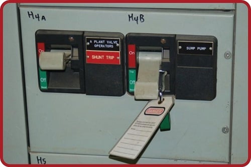
A close-up photograph shows one of these breaker panels, containing two separate three-phase circuit breakers inside:
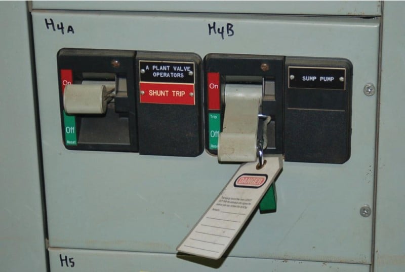
Note how the “Sump Pump” circuit breaker has been placed in the “off” position, its handle locked there by a padlock, a danger tag attached to notify any personnel of the reason for the breaker’s lock-out.
This next photograph shows a different brand of MCC (manufactured by Gould) where each unit contains not only a circuit breaker, but also an entire motor starter assembly (contactor, overload heaters, and associated switch contacts) for controlling a three-phase electric motor. One of these motor control “buckets” has been removed, revealing the line and load bus connections in the rear:
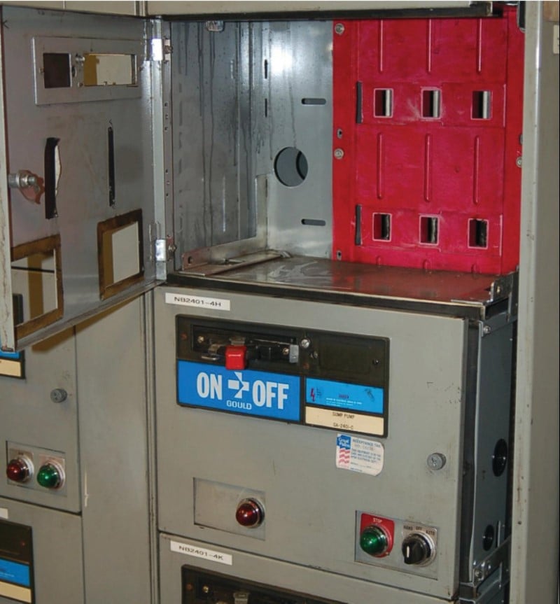
Industrial circuit breakers such as this are typically designed to be unplugged for ease of maintenance and replacement. If the “bucket” units are heavy, a lifting hoist is provided on the MCC to facilitate their removal and replacement.
Medium Voltage Circuit Breaker
Circuit breaker design and construction become more complicated at higher voltages, such as the voltage range extending from 2.4 kV to 35 kV commonly classified as “medium-voltage” in the electrical power distribution industry. Aside from being physically larger than low-voltage circuit breakers, medium-voltage circuit breakers are generally not self-tripping as low-voltage circuit breakers are. Rather, medium-voltage circuit breakers are electrically commanded to trip (and to close) by external devices called protective relays monitoring dangerous electrical conditions. Internally, these circuit breakers are equipped with “trip” and “close” electromagnet solenoids allowing the mechanism to be triggered by remote electrical signals.
Medium-voltage circuit breakers are designed to be unplugged from the breaker panel for maintenance and replacement. This is referred to in the electrical power industry as racking out a circuit breaker. Some circuit breakers “rack” by moving horizontally, sliding in and out of the panel on guide rails. Other circuit breakers “rack” by moving vertically, sliding up into and down out of the stationary panel terminals, as shown in the following illustration:

The primary purpose of being able to “rack” a medium voltage breaker into and out of its place in a breaker panel is to facilitate regular maintenance on the circuit breaker mechanism. Unlike the circuit breakers you find in your home, these units may be frequently cycled and will suffer definite wear with each actuation. After a certain number of closing/tripping cycles, the breaker must be removed from service for inspection and testing.
Racking out a circuit breaker also provides another advantage, and that is an extra measure of safety when securing a power circuit in a zero-energy state. When a circuit breaker has been locked into its “racked out” position, the load conductors serviced by this breaker absolutely cannot become energized even if the circuit breaker contacts were made to close. This is analogous to unplugging an electrical appliance from a wall receptacle: it cannot be powered up even if the switch is turned on!
An example of a vertically-racking circuit breaker is the General Electric “Magneblast” unit shown below, designed for use in power systems operating up to 15 kV. The particular unit shown rests on a wooden pallet in a storage area. Normally, it would be installed in a metal-clad breaker panel, its components hidden from direct view:

The six “stabs” seen on the top of this breaker unit engage with six sockets connected to the six bus-bar conductors inside the breaker panel (three for the three phases of the line supply, plus three more for the three phases of the load conductors). When this circuit breaker is “racked out,” it is dropped down so that these six stabs disengage from the bus-bar connections, making it impossible to energize the load conductors even if the breaker contacts close.
A detail not seen in this photograph is the hoisting mechanism necessary to lift this breaker into its “racked-in” position. Medium-voltage circuit breakers such as the General Electric Magneblast are quite heavy, requiring special “lift truck” frames to hoist into and out of their engaged positions in the circuit breaker panel.
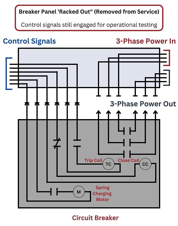
Not only does “racking out” a circuit breaker add an extra measure of safety for personnel working on the load circuit, but it also allows the breaker to be tested in-place without energizing the load. The electrical connections commanding the breaker to open (trip) and close may still be connected to the control circuitry even in the racked-out state, permitting such tests. The following illustration shows how such a test may be performed in the “racked-out” condition:
At medium-voltage and greater levels of potential, a significant design problem is how to rapidly extinguish the arc formed when contacts separate under load. Low-voltage circuit breakers simply rely on a wide and rapid enough separation of contact points to ensure the electric arc formed when the breaker trips cannot continue more than a fraction of a second. In medium-voltage circuits, both the heat output and the potential length of the electric arc formed by separating contacts is huge and therefore the arc must be extinguished as quickly as possible, both for personnel safety and for extending the operating life of the circuit breaker.
The original General Electric Magneblast circuit breaker design used a series of arc chutes, electromagnet coils, and pneumatic jets to direct the arc away from the separating contacts and thereby extinguish it rapidly. Other medium-voltage circuit breaker designs submerge the electrical contacts in an oil bath to keep them completely isolated from air so that an arc could never form. This oil has a high dielectric value (i.e. it is an excellent electrical insulator with a high breakdown rating), but needs to be tested on a regular basis to ensure good integrity.
A modern approach to the problem of extinguishing the arc drawn by opening circuit breaker contacts is to encapsulate the contacts inside of an air-tight vacuum chamber. This rear view of this GE Magneblast circuit breaker shows it retrofitted with vacuum contacts (the three white-colored components seen inside the breaker frame), replacing the old open-air contacts and arc chutes:

By removing all air from the vicinity of the contacts, there are no gas molecules to ionize when the contacts separate. Not only does this completely eliminate the problem of contact arcing, but it also permits the circuit breaker mechanism to perform its job with a shorter “throw” (less contact motion), since less gap distance is necessary to prevent current in a vacuum than in air. The only real challenge now is ensuring the integrity of the vacuum inside these chambers. This requires periodic testing of the contacts’ dielectric rating by maintenance personnel using high-voltage testing equipment.
An interesting feature of the GE Magneblast and other medium-voltage circuit breakers is the mechanism for actuation. These circuit breaker contacts must be moved swiftly and with significant force in order to ensure quick and repeatable make/break times. In order to achieve this rapidity of motion, the breaker is designed to actuate by the stored energy of large mechanical springs. A side-view of a Magneblast circuit breaker shows a pair of large coil springs used to trip and close the circuit breaker contacts:

Much like the spring on the hammer of a firearm, the springs inside this Magneblast circuit breaker provide the mechanical driving force for opening and closing the breaker’s three electrical power contacts. The act of opening or closing this circuit breaker is analogous to pulling the trigger of a firearm: a small mechanical movement unleashes the stored energy of these springs to do the actual work of rapidly opening and closing the contacts.
These springs are tensed (“charged”) by an electric motor in the times following an actuation cycle, so they will be ready for the next actuation. Typically these charging motors are powered by 125 VDC supplied by the substation’s “station power” battery bank, so they may operate even in the event of a total black-out condition where the substation loses AC line power from its incoming transmission lines. Indicator flags on the front of the circuit breaker reveal the breaker’s contact status as well as its spring charge status:

Green-colored flags seen on the front panel of this breaker show the contact status as “open” and the spring status as “discharged”. This circuit breaker is incapable of any action until its spring is charged. Once the spring has been charged, pushing the button labeled “Manual trip” will cause the breaker contacts to open, and pushing the button labeled “Manual close” will cause the breaker contacts to close.
A photograph of the front panel of a Westinghouse vacuum circuit breaker reveals the same basic indicators and manual controls seen on the (older) General Electric circuit breaker:

In this particular example, the actuating spring is charged, which means the breaker is in a state of readiness to switch from its present status (open, or tripped) to its opposite status (closed).
Both of these medium-voltage circuit breakers share another feature of interest: a mechanical counter tracking the number of close/trip cycles the breaker has experienced. The act of making and breaking high-power electric circuits takes a toll on the components of a circuit breaker – especially the contacts – and therefore this count value is a useful parameter for maintenance purposes. The breaker should be serviced at manufacturer-specified intervals of close/trip cycles, just like an automobile should be serviced at manufacturer-specified intervals of distance traveled.
High Voltage Circuit Breaker
At voltages 46 kV and above (classified as “high voltage” in the electrical power industry), the challenge of extinguishing the electric arc formed by separating breaker contacts becomes severe. Two popular strategies for mitigating contact arc in modern high voltage circuit breakers are oil immersion and gas quenching.
Oil Circuit Breaker
A set of three oil-bath circuit breakers (OCB’s) rated for 230 kV service is shown here, retired from service:

Each of the three circuit breakers (one for each line of the three-phase circuit) is mechanically linked by a common shaft at the top of the breaker tanks, so they all trip and close as one unit.
The fast and reliable actuation of such a bulky mechanism requires a large amount of stored energy, and in the case of the oil circuit breaker shown above the energy storage medium is compressed air. An on-board electric air compressor powered by “station power” maintains air pressure inside a pressure vessel, and this compressed air is directed to a piston actuator through solenoid valves to provide the actuation force necessary to move the breaker contact assemblies open and closed.
A view inside the enclosure on the far side of this oil circuit breaker reveals the air compressor (upper-right), compressed air storage tank (right) and actuation cylinder (middle):

The man shown in this photograph is pointing to a solenoid valve designed to pass compressed air to and from the piston actuator. A large-diameter black hose runs from this solenoid through the bottom of the enclosure, allowing compressed air from the cylinder to vent to atmosphere.
Gas Circuit Breaker
A more modern breaker design for 230 kV service is this gas-quenched circuit breaker unit, a mere fraction of the physical size of the oil circuit breaker shown previously:

The ribbed porcelain structures are the high-voltage terminals for this circuit breaker: three for the three-phase lines coming in, and three for the three-phase load terminals exiting. The actual contact assemblies reside in the gas-filled horizontal metal tubes (“tanks”). It is striking to note that the same current interruption and isolation functions performed by the gigantic oil-filled tanks of the retired circuit breaker previously shown are performed by this relatively tiny gas-quenched breaker.
The gas inside the breaker’s tanks is sulfur hexafluoride, a very dense gas (about 5 times denser than air) with excellent electrical insulating and arc-extinguishing properties. SF\(_{6}\) gas is contained in these breaker contact chambers under pressure to maximize its dielectric breakdown strength (its ability to withstand high voltage without ionizing and passing current across the gap between the circuit breaker’s open contacts). SF\(_{6}\) gas is non-toxic and safe to handle.
Like the large oil-filled circuit breakers seen previously, this SF\(_{6}\) circuit breaker has an enclosure on one side where the actuation and control components are located. Inside this enclosure we see a large stack of Belleville spring washers (the dark-colored discs located in the center of the enclosure), which are used as the mechanical energy-storage medium instead of compressed air. This stack of spring-steel washers is compressed by an electric motor and gear mechanism, then the spring tension is released through another mechanism to close and trip the breaker’s contacts on demand. As usual this charging motor receives its power from the uninterruptible “station power” supply of the substation, allowing the breaker to actuate even in the event of a total “blackout” condition:

Inside this enclosure we also see a small pair of pushbuttons (one red, one green) just below and to the right of the Belleville washer stack for manually closing and tripping the breaker, respectively. The common color coding used in the United States for electric power switchgear is red for energized, green for de-energized. This may seem backward to most people familiar with red and green traffic lights, where red means “stop” and green means “go,” but the concept here is one of safety: red means “dangerous” (power on) while green means “safe” (power off).
It should be noted that most of the time these high-voltage circuit breakers are triggered remotely, rather than manually by someone standing near them. These command signals may come from a manual switch located in the control room, or from some automatic circuit such as a protective relay instructing the breaker to open due to an abnormal system condition.
The nameplate photographed on a similar SF\(_{6}\) circuit breaker reveals some interesting features:

According to this nameplate, the normal operating pressure for the SF\(_{6}\) gas is 98.6 PSI. A low-pressure alarm triggers if the SF\(_{6}\) gas pressure happens to fall below 85 PSI. When opening (tripping), the circuit breaker only takes 3 cycles’ worth of time at 60 Hz to completely interrupt the current. One solenoid coil closes the breaker, and that coil requires a signal of 125 volts DC at just over 3 amps of current. The breaker’s contacts may be tripped by energizing one or more redundant solenoid coils at 125 VDC and 1.8 amps (each). In either direction, the breaker’s actuation is powered by a pre-charged spring, much like the 230 kV breaker seen previously. This particular breaker is rated for 123 kV at 2000 amps full-load.
Sulfur hexafluoride gas circuit breaker technology is popular for higher voltage applications as well, such as these 500 kV circuit breakers seen here:

In this application, where three separate circuit breaker units independently interrupt current for the three-phase power lines, there is no mechanical link to synchronize the motion of the three contact sets. Instead, each single-phase circuit breaker actuates independently.
So far all of the high-voltage circuit breakers shown in previous photographs are of the dead tank type, where the structure housing the interrupting contact(s) is maintained at ground potential (i.e. the outside surface of the circuit breaker mechanism is electrically “dead”). Some high-voltage circuit breakers are built such that their interrupting assemblies are at line potential, the entire breaker suspended above ground from insulators. This type of circuit breaker is called a live tank, because the “tank” containing the contact(s) operates at a high voltage with respect to earth ground. A photograph of a 500 kV, single-pole, SF\(_{6}\)-quenched, live tank breaker appears next:

The actuating mechanism for this live-tank breaker is housed in the “can” assembly seen at the base, where the vertical insulator meets the steel supporting tower.
Another 500 kV, single-pole, live-tank circuit breaker assembly appears in the next photograph, this particular breaker being an older unit using compressed air as the interrupting medium rather than sulfur hexafluoride gas:

Air nozzles powered by hundreds of PSI of compressed air are used to “blow out” the arc formed when the circuit breaker’s contacts separate. These air nozzles are not visible in the photograph, being internal to the circuit breaker’s construction. An interesting feature of this style of circuit breaker is the loud report generated when it trips: the sound of the compressed air jets extinguishing the arc across the separating contact poles within the breaker is not unlike that of a firearm discharging.
Multiple series-connected contact assemblies comprise this circuit breaker, distributing the energy of the arc across multiple points in the breaker assembly rather than across a single contact. This is evident in the photograph as multiple clusters of “tanks” on the top of the left-hand assembly, as well as the second live-tank assembly connected in series to the right. Such arrangements are necessary because air is a less effective medium for extinguishing an electric arc than either oil or SF\(_{6}\) gas.
Reclosers for Transient Faults
A special type of medium-voltage circuit breaker used to quickly interrupt and re-establish power in distribution lines is called a recloser. Reclosers are designed to trip if ever a distribution line suffers a “transient” (momentary) fault due to some natural event such as a lightning strike causing an insulator to “flash over” to ground or a tree branch touching one or more line conductors, then automatically re-close moments later to test whether or not the fault still persists. If the fault clears on its own – a common occurrence with tree branches, as the branch may break off or burn away following the initial arc – then the recloser remains closed and continues providing power to customers. By some estimations transient faults account for 70% to 90% of all faults occurring on overhead power lines. If non-reclosing fault protection were applied to all distribution and transmission lines, extended interruptions of electric power service would be far more common than they are now.
If you have ever experienced momentary cessations of electrical power service to your home or business where the power “blinks” off and on in rapid succession, you have experienced a recloser at work. The recloser opens as soon as an overcurrent condition is detected, then recloses briefly to “test” for continued presence of the fault. If the fault persists, the recloser trips again and then recloses once more to “re-test” for the fault. If the fault has cleared by then, the recloser remains closed and restores normal power service to customers. Only if the fault persists after multiple “shots” does the recloser remain in the tripped (open) state and waits for line crews to repair the fault.
Reclosers are typically located some distance “downstream” of the substation, to isolate certain remote portions of the distribution network. Circuit breakers at the substation provide protection for each distribution line as a whole:

A typical recloser resembles a “circuit breaker on a stick,” located near the top of a distribution power pole near the line conductors. Modern reclosers use SF\(_{6}\) gas quenching to extinguish arcing resulting from the interruption of high-magnitude fault currents. Legacy reclosers typically employed oil quenching. This photograph shows a modern (SF\(_{6}\)-quenched) recloser, with its three phase current-interrupting contact units clearly visible:

The grey enclosure located near ground level on this pole contains the protective relay responsible for issuing the “trip” and “close” signals to the recloser’s coils. Current transformers located within the recloser provide isolated sensing of line current to the reclosing relay, necessary for detecting any overcurrent conditions that might result from a transient fault. Each attempt by the reclosing relay to re-close the breaker is called a shot. If the reclosing relay fails to clear the fault by a certain number of shots, it enters the lockout state whereby the recloser remains open and must be re-closed by human intervention.
Distribution line reclosers, unlike circuit breakers located in substations, cannot rely on an auxiliary “station power” energy source for opening and closing its line-interrupting contacts. Therefore these small units utilize AC line voltage as the actuating power for the contacts. Low-voltage “trip” and “close” circuits still exist for control purposes, but the actual energy source for rapid tripping/reclosing cycles comes from the AC line itself.
The principle of automatic reclosing may be applied to transmission lines as well as distribution lines, but new challenges exist at this level of a power grid. When transmission lines serve to interconnect distributed generating stations, interruption of that line for any significant time invites generator de-synchronization. Recall that AC generators, once synchronized with each other and connected in parallel on a common grid circuit, tend to remain synchronized with each other as though their mechanical shafts had become coupled. If a circuit breaker opens along a transmission line system and de-couples generators from each other, those generators will be free to fall out of synchronization. Reclosing that circuit breaker when those generators are out of sync with each other can be disastrous. Automatic reclosing at the distribution line level of a power grid, therefore, must either be fast enough that generators will not have enough time to fall out of sync with each other, or blocked by other protective relay logic to prevent reclosure in an out-of-sync situation.
REVIEW:
-
Circuit breakers remove power from a branch circuit in the case of a current overload.
-
High-voltage circuit breaker methods include oil bath and gas quenched, respectively activated by the stored energy of compressed air and steel springs.
-
Disconnects remove power to a branch circuit when power is removed by means of an upstream circuit breaker device.
-
Reclosers can test for momentary overcurrent faults, and if the fault is quickly removed, power to the branch circuit can be restored.
If you are interested in more content about electrical power control systems, check out these calculators:
Related textbook pages:
- Understanding Electrical Power Grids
- Introduction to Protective Relaying
- Instantaneous and Time-Overcurrent Protection
- Auxiliary and Lockout Relays
Related Technical Articles:
- Understanding Power Quality, Monitoring, and Correction
- Active Power, Reactive Power, Apparent Power, and the Role of Power Factor
- Control and Visualization of Power Plant Data Through SCADA Systems
