 Facebook
 Google
 GitHub
 Linkedin
Introduction to Protective Relaying

What are Protective Relays, or Protection Relays?
Protective relays are used in industrial power generation and supply systems to open and isolate branch circuits in the case of excessive current. They are activated by means which are not dependent on a continual AC supply. They include both mechanical induction disks in older systems, and more modern electronic varieties.
Circuit breakers used in residential, commercial, and light industrial service are self-tripping devices: they internally sense the amount of electric current going through them, automatically opening when that current exceeds a pre-determined level. Circuit breakers used in medium-voltage (2.4 kV to 35 kV) and higher-voltage applications, however, must be triggered to trip by external devices. This remote-control philosophy not only eliminates the technical problem of incorporating accurate and rugged current-sensing devices inside the body of a large circuit breaker, but it also opens the possibility of having these circuit breakers trip and close based on practically any condition imaginable, not just overcurrent.
What is a Protection Relay?
An electrical device designed to detect some specified condition in a power system, and then command a circuit breaker either to trip or to close in order to protect the integrity of the power system, is called a protection, or protective, relay. As we will see in this chapter, there is a wide variety of protective relay types and functions: overcurrent is just one of a great many power system conditions monitored and guarded against by protective relays.
The following photograph shows a pair of protective relays installed in the control panel for a medium-voltage power distribution circuit breaker. The relay on the left (just above the manual trip/close control switch) is a “time overcurrent” unit, designed to automatically trip the circuit breaker based on the product of current and time. The relay on the right (just above the “Reclose Cutout” switch) is a reclosing relay, designed to automatically trip the circuit breaker in the event of an instantaneous overcurrent event (e.g. a tree branch short-circuiting a power line) and then automatically re-close the breaker to test whether or not the fault has cleared. If the fault clears on its own, the breaker remains closed; if the fault remains, the reclosing relay will trip the breaker again.

If ever you have experienced the electric power service to your home “blink” a few times and then resume as normal, you have been the beneficiary of a reclosing relay. If it were not for the reclosing relay’s programmed strategy of multiple attempts to restore power, your electric service would be shut off for extended periods of time following any momentary power line fault.
An illustrative diagram shows how a simple protective relay monitors and interrupts power. The protective relay senses load current via the three line current transformers (CTs), closing a “trip” contact to trip the circuit breaker if ever the line current exceeds any limits pre-programmed into the relay:

Inside most remote-tripping circuit breakers is an auxiliary contact (sometimes designated “52a”) connected in series with the trip coil. This auxiliary contact is actuated by the same mechanism actuating the three large power contacts inside the circuit breaker, and thus the auxiliary contact will be closed when the breaker is closed and open when the breaker is tripped. The purpose of this normally-open auxiliary contact is to interrupt power to the trip coil once the circuit breaker has reached the trip position, so that the trip coil does not overheat (nor will the station battery be needlessly discharged) if the protective relay happens to continuously output a trip command signal.
Note the use of a 125 volt DC “station battery” supply for the circuit breaker’s “trip” circuit. A battery provides uninterruptible DC power, so that breakers may be tripped and closed even in the event of a total AC power failure in the facility. A photograph of the station battery for a large substation is shown here:
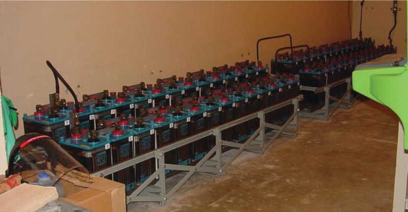
Protective relay circuits have been powered by station batteries for many decades, because a large battery bank is the simplest form of uninterruptible power supply (UPS) in existence. A trickle-charging AC-to-DC power supply keeps the station battery in a constant state of full charge while AC power is available. In the event of an AC power interruption, all protective relays and other critical instrumentation in the facility will continue to operate normally. Even the most modern digital protective relays operate on the traditional 125 VDC supply voltage rather than 120 VAC as is common with other types of industrial controls.
Induction Disk Protective Relay
Protective relays have seen widespread use in industrialized power systems since the early twentieth century, with continued technological development. The earliest protective relay technologies were electromagnetic in design, a great many of them based on the “induction disk” design whereby out-of-phase AC magnetic fields caused an aluminum disk to torque like the rotor of an induction electric motor. The induction disk technology became popular as the basis for rotating-disk watt-hour meters used in residential and commercial electric power service as well.
An example of an induction disk protective relay typical of the genre is seen here, a General Electric model 121AC overcurrent relay:

This relay uses an aluminum disk approximately 4 inches in diameter to sense and time overcurrent conditions. The disk is slowly rotated by the torque generated from a set of electromagnet coils energized by current received from a current transformer (CT). In order for the disk to rotate at all, the coils’ induced torque must exceed the restraining torque applied on the disk’s shaft by a spiral spring. This amount of current necessary to overcome the spring’s torque is called the pickup current value for the induction relay. Current in excess of the pickup value causes the disk to slowly rotate, the speed of rotation being a function of current magnitude (more current = faster rotation). If the disk rotates all the way to its end-point, it closes an electrical contact to signal a “time-overcurrent” trip, causing the system’s circuit breaker to trip open and interrupt current.
Protective relays such as this General Electric model were built to be “drawn out” of their sockets for easy maintenance and replacement. The relay shown in the above photograph has already been drawn out of its case for inspection.
Electronic Protection Relays
Later protective relay designs used electronic circuits rather than electromagnetic mechanisms to detect and time overcurrent conditions. This Basler model BE1-79M “reclosing” relay is illustrative of early solid-state generation protective relays:

Like the earlier generation induction-disk relays, this electronic relay is also a “draw-out” style, permitting convenient maintenance and replacement.
A more modern example of a protective relay is this Schweitzer Engineering Laboratories model 551 overcurrent/reclosing relay:
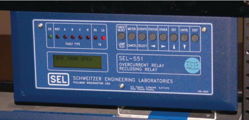
The accuracy, stability, and reliability of modern microprocessor-based protective relays is such that there is no longer a need to regularly remove them for service and replacement. This is why the traditional “draw-out” design has been replaced by a more permanent rack-mount design.
Another advantage of a microprocessor-based relay design is the ability to communicate digitally with other microprocessor-based systems. This permits remote querying of the relay’s status and parameter settings. Additionally, the digital memory capabilities of a microprocessor-based relay allows for power instrument data (voltage, current, phase shift, timestamps, etc.) to be stored, so that personnel may determine the sequence of events leading up to a breaker trip.
An interesting footnote to modern protective relays is their persistent use of anachronistic terms. Even in the most modern protective relays such as the Schweitzer model 551 shown previously, you will find parameters inside the relay designated torque control, time dial, pickup, and dropout: all terms designed to describe moving components inside an electromagnetic relay mechanism such as the old General Electric model 121AC induction-disk unit. Protective relay controls were developed and perfected for so many years using electromagnetic relay technology that the nomenclature remains in common use even though the mechanisms inspiring these terms are obsolete. It is for this reason that electromechanical relay technology will be presented in this book’s discussions of protective relay functions: to orient the reader to the origins of the terms so that they will make more sense when encountered in modern protective relays.
As you can see, the strategy of using independent “relay” devices to command a large power circuit breaker to trip is a much more sophisticated way of ensuring power system protection and reliability than constructing each circuit breaker with its own internal overcurrent mechanism. This is truly an “instrumentation” approach to electric power control: intentionally locating the intelligence of the system to a set of dedicated control devices which may be upgraded and reconfigured on demand to meet continually changing needs.
REVIEW:
-
Protective relays measure current in each branch of a 3-phase circuit testing for anomalies.
-
Protective relays often use DC coils supplied by batteries to allow operation even in total AC power failure.
-
Older induction disk relays employed mechanical methods of disconnecting power in the event of excessive current, further reducing dependence on a constant AC supply.
If you are interested in more content about electrical power control systems, check out these calculators:
Related textbook pages:
- Understanding Electrical Power Grids
- Instantaneous and Time-Overcurrent Protection
- Auxiliary and Lockout Relays
Related Technical Articles:
- Understanding Power Quality, Monitoring, and Correction
- Active Power, Reactive Power, Apparent Power, and the Role of Power Factor
- Control and Visualization of Power Plant Data Through SCADA Systems
