 Facebook
 Google
 GitHub
 Linkedin
Distance (21) Protection
What Is a Distance Protection Relay?
Distance relaying is used to detect faults on long-distance lines, pinpointing not only the fault condition but also measuring the distance between the current sensing mechanism and the fault location in the wire.
A form of protection against faults on long-distance power lines is called distance relaying, so named because it is actually able to estimate the physical distance between the relay’s sensing transformers (PTs and CTs) and the location of the fault. In this way, it is a more sophisticated form of fault detection than simple overcurrent (e.g. 50 or 51 relay). The ANSI/IEEE number code designation for distance relaying is 21.
Distance Relay Reach
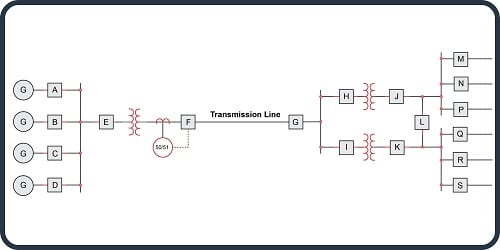
In order to understand the rationale for distance relaying on transmission lines, it is useful to recognize the limitations of simple overcurrent (50/51) protection. Consider this single-line diagram of a transmission line bringing power from a set of bus-connected generators to a substation at some remote distance. For simplicity’s sake, only one protective relay is shown in this diagram, and that is for breaker “F” feeding the transmission line from the generator bus:
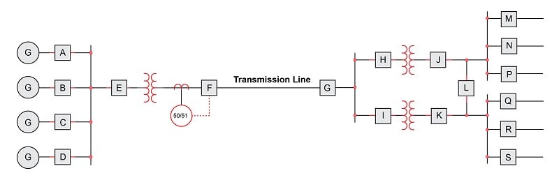
The purpose of the overcurrent relay tripping breaker “F” is to protect the transmission line and associated equipment from damage due to overcurrent in the event of a fault along that line, and so the relay must be set appropriately for the task. The amount of fault current this relay will see depends on several factors, one of them being the location of the fault along the transmission line. If we imagine a fault occurring on the line near breaker “F,” the fault current will be relatively high because it is close to the generator bus and therefore experiences little transmission line impedance to limit current. Conversely, if we imagine a fault farther out on the transmission line (closer to breaker “G”), the amount of current caused by the fault will be less, even for the exact same type of fault, simply due to the added series impedance of the transmission line’s length (if \(I = {V \over Z}\) and \(Z\) increases while line voltage \(V\) remains the same, \(I\) must decrease). Any similar fault further downstream of the generators – such as a fault in one of the transformers in the substation – will draw even less current through breaker “F” than a similar fault on the transmission line for the same reason of greater series impedance.
An important concept in protective relaying is that of protection zones. Protective relays exist to protect the power system from damage due to faults, and they do so by tripping circuit breakers to interrupt the flow of power to a fault. However, in the interest of maintaining power to customers, it is best for protective relays to only trip those breakers necessary to clear the fault, and no more. Thus, protective relays are designed to trip specific breakers to protect limited “zones” within the system. In this next single-line diagram, we show the same system with rectangular zones overlaid on the system components:
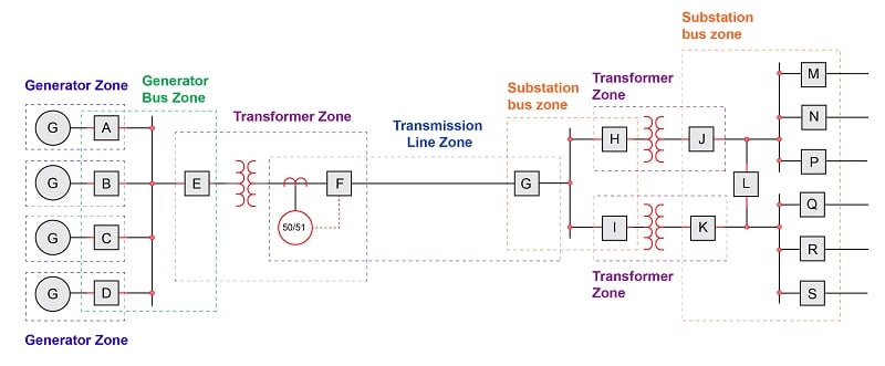
This zone diagram makes it clear that breaker “F” and its associated overcurrent relay should only act to protect the transmission line from fault-induced damage. If a fault happens to occur within one of the transformer zones within the substation, we would prefer that fault be cleared by the protective relays and breakers for that transformer alone (i.e. either breakers “H” and “J” or breakers “I” and “K” depending on which transformer faults), in order that power be maintained in the rest of the system. This means the overcurrent relay controlling breaker “F” needs to be sensitive to faults within the transmission line zone, but insensitive to faults lying outside of the transmission line zone. If the 50/51 relay happened to overreach its zone and trip breaker “F” because of current sensed from a fault in one of the substation transformers, it would unnecessarily cut power to the entire substation, with a loss of power to all loads fed by that substation.
At first, the problem of overreaching may seem simple to solve: just calculate the maximum fault current in the transmission line due to any worst-case fault outside of that zone, and be sure to set the overcurrent relay so that it will only trip at some current greater than that amount, or set it so it will trip after a longer time delay than the substation relay(s) will trip, to give the substation relays a chance to clear the fault first.
The weakness of this approach is that fault location is not the only factor influencing fault current magnitude. Another important variable is the number of generators in service at the time of the fault. If one or more of the generators happens to go off-line, it reduces the generator bus’s ability to supply current to a fault. Another way of saying this is that the power source’s impedance changes with the number of generators on-line. This means any given fault downstream of breaker “F” will cause less fault current than it would if all generators were on-line.
This causes a problem for the “reach” of the overcurrent relay controlling breaker “F.” With reduced current capacity from the generator bus, the same relay setting that worked well to protect the transmission line zone will now be too high for faults lying toward the far end of that line. In other words, the overcurrent relay may underreach and fail to trip breaker “F” because the amount of fault current for a transmission line fault is now less than what the relay has been set to protect against, and all because we happen to have fewer generators on-line to supply power. The impedance of the transmission line and fault may be precisely the same as before, but the overcurrent relay will not trip because the circuit’s total impedance has changed due to fewer generators being on-line.
We see that the location of a fault within a long-distance power distribution system cannot be reliably detected by sensing current alone. In order to provide more consistent and reliable zone protection for the transmission line, we need a form of protection better able to discriminate fault location. One such method is to measure the impedance of the protected zone, based on current and voltage measurements at the entry point of power into that zone. This is the fundamental concept of distance protection: calculating the impedance of just the protected zone, and acting to trip breakers feeding power to that zone if the impedance suggests a fault within the boundaries of that zone.
Line Impedance Characteristics
Capacitance, inductance, and resistance are all naturally present along miles of power line conductors: capacitance due to electric fields existing within the separation of the lines from one another and from earth ground by the dielectric of porcelain insulators and air; inductance due to the magnetic fields surrounding the lines as they carry current; and resistance from the metal conductors’ length.
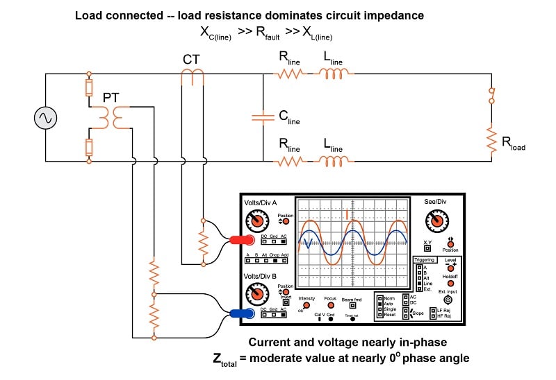
The capacitive nature of a power line is evident when that line is open-circuited (i.e. no load connected). For the next few schematic diagrams, only a single phase (one “hot” conductor and one “neutral” conductor) will be represented for the sake of simplicity:
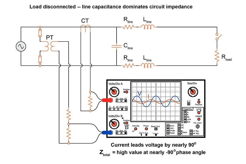
Here, an oscilloscope shows the relative magnitudes and phase shifts of the voltage and current waveforms, allowing us to make determinations of total circuit impedance (\(Z = {V \over I}\)).
Under typical load conditions, the resistance of the load draws a much greater amount of current than an open-circuited line draws due to its own capacitance. More importantly, this current is nearly in-phase with the voltage because the load resistance dominates circuit impedance, being substantially greater than the series reactance caused by line inductance while being substantially less than the parallel capacitive reactance:
A significant fault behaves like a very low resistance connected in parallel. This not only decreases total circuit impedance but also shifts the phase angle closer toward \(+90^{o}\) because now the line inductive reactance is substantial compared to the resistance of the fault. Real transmission lines tend to exhibit shorted impedance phase angles nearer 70 degrees rather than 90 degrees, owing to the effects of line resistance. The exact line impedance phase angle depends on conductor size and separation:
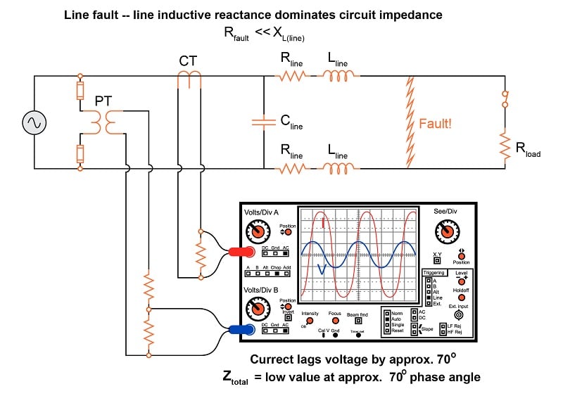
Since line inductance is a fairly linear function of line distance (a longer power line means more inductance, given a fixed inductance-per-mile value), and this inductive reactance is the dominant factor limiting fault current, the magnitude of the fault current becomes an approximate indication of distance between the instrument transformers and the fault.
Using Impedance Diagram to Characterize Faults
Oscilloscope displays showing the raw voltage and current waveforms are clumsy representations of line impedance. Better visual representations for impedance exist, the most popular being a phasor diagram for line impedance with resistance (\(R\)) on the horizontal axis and reactance (\(X\)) on the vertical axis, commonly referred to as an R-X diagram. The three line examples shown in the previous section using the oscilloscope are shown in phasor format here:
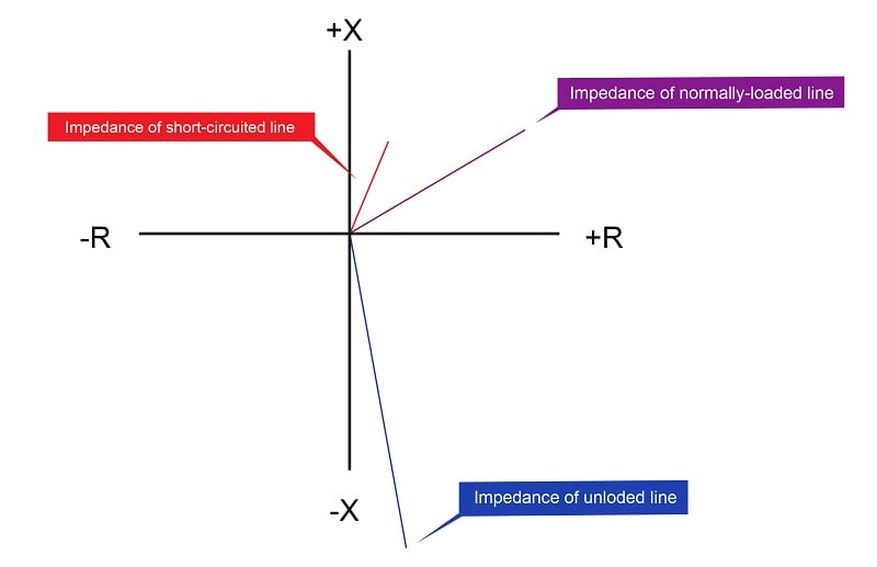
Keep in mind that these phasors represent impedance, and as such a short-circuited (faulted) condition is shown as a short phasor, while an unloaded condition is shown as a long phasor. It should also be noted that these impedances, while calculated from measurements of voltage and current, do not change unless the line, load, or fault characteristics change. If the system voltage were to sag due to a generator problem, for example, the impedance phasor representing the combined effects of line and load impedance would not be altered. Any protective relay operating on impedance would therefore ignore such changes, and trip only if the line’s characteristics were to change. This is precisely the behavior we need from a “distance” relay, enabling it to discriminate line faults better than a simple overcurrent relay ever could.
For a normal load condition, the impedance phasor will be significantly longer than that of the line’s full length (i.e. much higher impedance) with an angle significantly less than that of the line impedance alone:
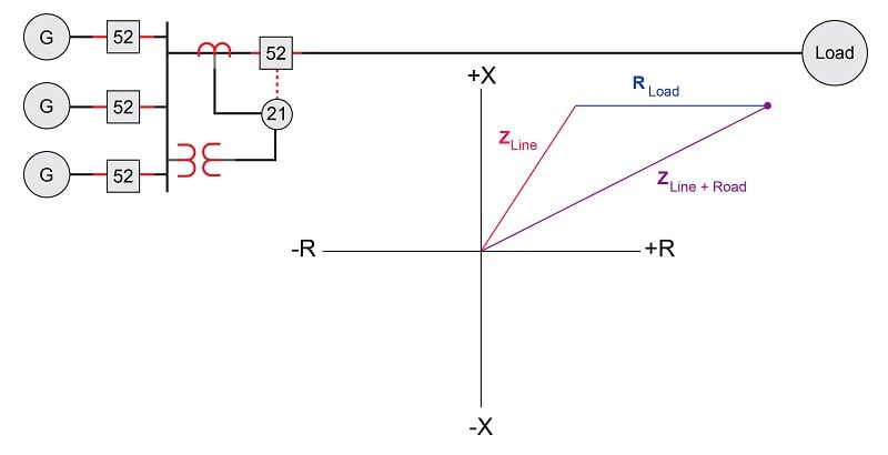
Short-circuit faults at various locations along a transmission line will cause the impedance phasor to vary primarily in magnitude and angle. Recall that during fault conditions, the resistance and reactance of the power line itself is the dominant impedance limiting fault current. The actual fault is predominantly resistive, with a very small impedance value.
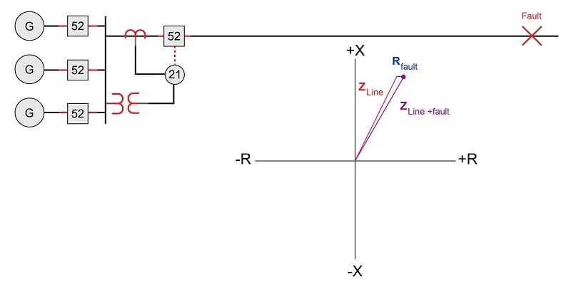
For a fault far removed from the relay, the impedance phasor will be long (i.e. relatively high impedance) with angle nearly equal to that of the line impedance alone:
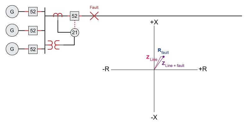
For a fault closer to the relay, the impedance phasor will be short (i.e. low impedance) with angle slightly less than that of the line impedance alone:
The goal of a distance relay (ANSI/IEEE code 21) is to trip its circuit breaker(s) if a fault occurs within its programmed “reach” and to ignore both normal operating loads and faults lying outside its reach.
If additional sources of electrical power are connected to the far end of the transmission line, it is possible for the distance relay to sense reverse power flow. Consider a case where a short-circuit fault occurs on the generator bus shown in this single-line diagram:
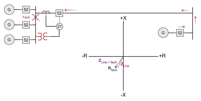
A fault to the left of the distance relay manifests as high current and low voltage just like a fault on the transmission line, but since the current waveform is inverted (180\(^{o}\) phase shift) due to the opposite direction of fault current, the impedance phasor ends up in an entirely different quadrant of the R-X diagram. If the goal of the distance relay is to protect the transmission line, we need it to ignore such faults, because to operate on such a fault would be an example of overreach, the distance relay “reaching into” the generator bus zone where it should be concerned with the transmission line zone.
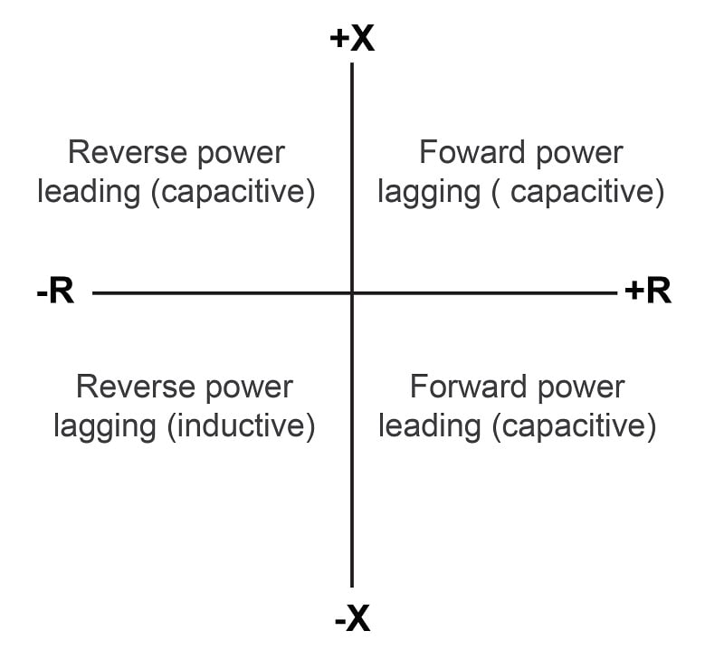
Each of the R-X diagram’s quadrants may be labeled in terms of power direction and power factor, either “lagging” (predominantly inductive) or “leading” (predominantly capacitive):
Distance Relay Characteristics
A primitive electromechanical impedance relay design for detecting faults along long-distance transmission lines uses a simple balance-beam mechanism to sense when the ratio of line current to line voltage (\(I \over V\)) becomes excessive. It will trip if ever the impedance became too small (i.e. too much \(I\) and too little \(V\)):
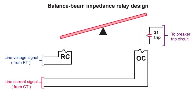
This relay’s operating coil (OC) is energized by a current transformer signal, while the restraint coil (RC) is energized by a potential transformer signal. During normal and unloaded operation, when voltage is high and current is moderate-to-low, the attractive force exerted on the beam by the restraint coil’s magnetic field exceeds the attractive force exerted on the beam by the operating coil’s magnetic field, and the trip contact remains open. If, however, a fault condition occurs on the transmission line, current will dramatically increase while voltage decreases. This combination of changes causes the operating coil’s magnetic attraction to exceed that of the restraint coil, causing the beam to tilt in a clockwise rotation, closing the trip contact to send a DC tripping signal to the circuit breaker’s trip coil.
An important characteristic of this crude impedance relay design is that it is insensitive to phase shift between voltage and current. In other words, it does not discriminate between line impedance values having different phase angles, but will trip based solely on a minimum impedance magnitude.
The “reach” of this impedance relay may be plotted on an R-X phasor diagram as a circle centered around the origin of the graph:
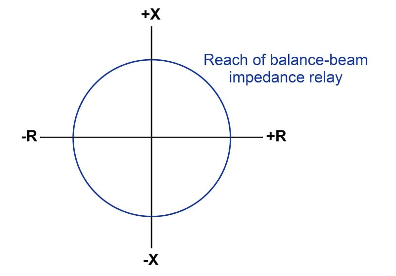
Any line condition placing the impedance phasor tip within this circle will cause the relay to trip. Any line condition placing the impedance phasor tip outside this circle will cause the relay to be restrained (i.e. it will not trip). Thus, the reach of this relay is represented by the radius of the circle sketched on the R-X diagram.
As you can see, this design of distance relay will trip for reverse-power conditions just as easily as it will trip for forward-power conditions. Since we generally wish to de-sensitize distance relays from “reaching backward” into a reverse protection zone, we must find some way to limit the impedance relay’s tripping sensitivity in the reverse direction.
For the primitive balance-beam design, one solution to the problem of reverse-power sensitivity is to use a directional relay in conjunction with the distance relay to block the distance relay’s action during reverse-power conditions. The trip contact of a directional relay could be wired in series with the trip contact of the impedance relay, such that the only way to trip the breaker is if both the impedance relay and the directional relay agree. We may represent this blocking behavior by drawing a line called a blinder on the R-X diagram showing a threshold beyond which the impedance relay cannot operate:
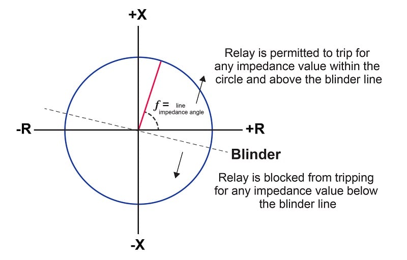
Phase-shifting components inside the directional relay mechanism tilt its blinder characteristic slightly clockwise from its natural (horizontal) characteristic. As you can see, the blinder prevents all operation in the lower-left quadrant, restricting operation of the impedance relay primarily to the upper-right and upper-left quadrants, with only a small portion of the lower-right quadrant active.
Blocking the impedance relay’s action using a directional relay is a crude solution for a crude relay design. Much better distance relay characteristics have been developed since.
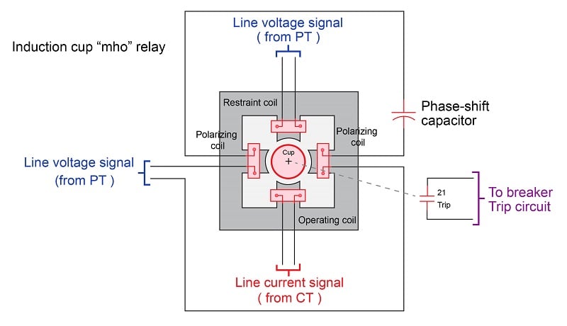
Induction Cup Distance Relay
A major breakthrough in distance relay design came with the advent of the induction cup mechanism. This is similar in design to the induction disk mechanism explained in the section on time-overcurrent relays, but designed to operate very quickly rather than very slowly. An induction cup mechanism closely resembles a two-phase induction motor, where a small cup-shaped metal rotor is surrounded by two sets of electromagnet poles. Maximum torque will be induced on the rotor when the stators’ magnetic fields are 90 degrees phase-shifted from one another in time. When a positive torque is applied to the cup, it rotates on its axis to close a trip contact, sending DC power to the circuit breaker’s trip coil:
The amount of torque induced on the rotor (cup) is described by the following formula:
\[\tau = VI \cos (\theta - \phi) - KV^2\]
Where,
\(\tau\) = Torque exerted on induction cup
\(V\) = Line voltage
\(I\) = Line current
\(\theta\) = Phase angle of voltage with respect to current
\(\phi\) = Phase angle of maximum rotor torque
\(K\) = Restraint constant of relay
Algebraically solving for the relay constant \(K\) at a point of zero torque (the pick-up value for the relay) yields units of mho, or inverse ohms, which is why this mechanism is called a “mho element”:
\[0 = VI \cos (\theta - \phi) - KV^2\]
\[0 = {I \over V} \cos (\theta - \phi) - K\]
\[K = {I \over V} \cos (\theta - \phi)\]
\[K = \left[{\hbox{Amps} \over \hbox{Volts}}\right] [\hbox{unitless}]\]
\[K = \left[\hbox{Mhos}\right]\]
With no phase-shifting capacitor, this mechanism will be maximally sensitive to impedance values of \(+90^{o}\), with a characteristic resembling a circle passing through the origin of an R-X diagram:
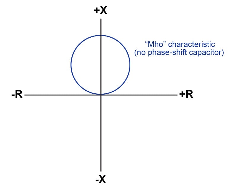
This relay’s reach is defined as any impedance falling within the circle, just as we defined the reach of the impedance relay. The difference here, of course, is that the “mho” distance relay is entirely insensitive to conditions within the lower quadrants of the R-X diagram.
With the addition of the phase-shifting capacitor to the induction cup polarizing coil circuit, the circular characteristic becomes tilted. Ideally, the angle of this tilt is set to match the impedance phasor angle of the transmission line so as to make the relay maximally sensitive to faults along the line.
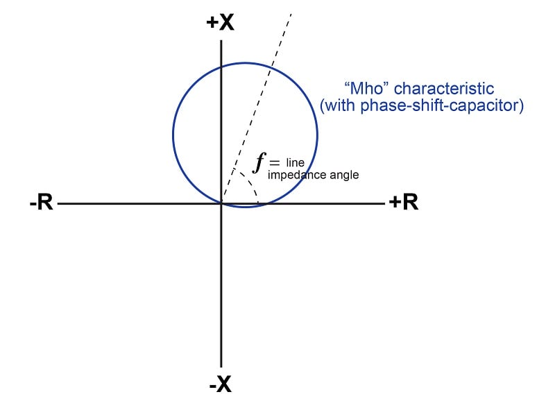
With a tilted axis, the longest chord within the circle beginning at the origin of the R-X diagram is one matching the axis of tilt. Therefore, the highest impedance value capable of operating the relay and tripping the circuit breaker is one where the phase angle matches the tilt: indicative of a low-resistance fault at the end of a transmission line, assuming the circle’s diameter is proportional to the length of that line. Measured impedances at any other angle must be lower (i.e. a “heaver” loading condition) in order to operate the distance relay and trip the breaker.
If we compare circle characteristics for the simple impedance relay versus the “mho” relay capable of tripping at the same end-of-line fault condition, we see a remarkable contrast:
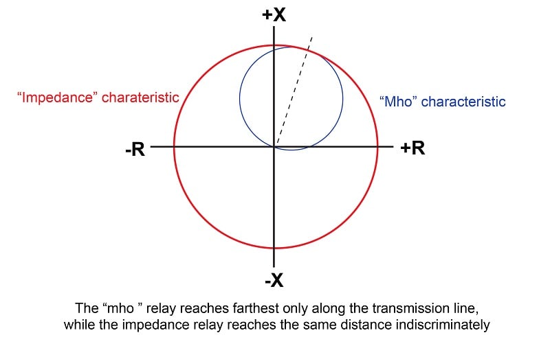
Both relays have the exact same reach at the transmission line’s impedance angle, but the impedance relay’s reach extends omnidirectionally for all phase angles and power flow directions, while the mho relay’s reach is optimized for the forward power direction and the line’s impedance, making it far more selective to faults along that line.
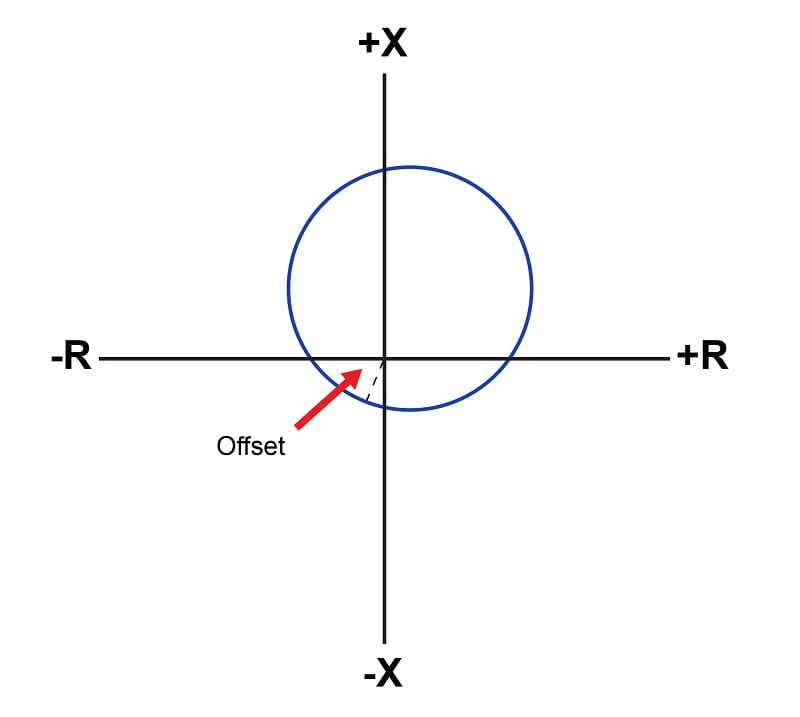
In some applications it is desirable to have the distance relay sensitized to certain values of reverse impedance (i.e. the lower-left quadrant on the R-X diagram). The induction cup relay mechanism is capable of having its circular reach characteristic “offset” with additional components so that the circle covers part of every quadrant like this:
Another variation on the “mho” characteristic is to equip the distance relay with multiple elements, each one with a different reach. The purpose of this is to provide backup protection for other zones by allowing the distance relay to overreach its primary protection zone:
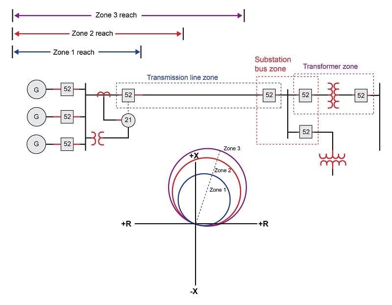
Since distance relays trip whenever the tip of the impedance phasor falls within the prescribed area on the R-X diagram, at first it may seem as though zones 1 and 2 are pointlessly redundant to zone 3, since any fault lying within one of the inner zones will certainly be within the reach of the furthest zone. Indeed, this would be the case if all three distance elements operated at the same speed. However, if the zone 2 reach is purposely delayed in its action to be slower than zone 1, and zone 3 purposely delayed to make it slower than zone 2, the distance relay will serve to provide remote backup protection for the substation bus and transformer zones in the event the protective relays and/or breakers for those zones fail to properly clear a fault.
The following photograph shows a pair of Westinghouse electromechanical distance relays mounted next to a pair of time-delay units, each timer providing a different amount of delay for each of the two zones of protection afforded by the distance relays:

In the age of microprocessor relays, this design philosophy of physically wiring time-delay relays to the outputs of electromechanical protective relays for multi-zone protection may seem archaic, but it represents standard practice in distance relaying for a number of decades. Of course, modern microprocessor-based distance relays are able to perform all the necessary zone timing functions along with distance-sensing fault detection within the same unit, and do so with a degree of precision unthinkable with electromechanical relays.
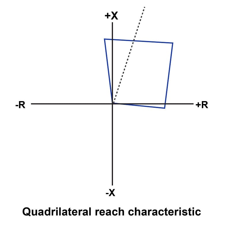
Modern microprocessor-based distance relays are not constrained to circular reach characteristics either, and thus may be programmed to implement a variety of interesting reach functions. Although the traditional “mho” characteristic is still available as an option within digital distance relays, another form of reach called the quadrilateral (or “quad” for short) is often provided, whereby the distance relay may be configured to trip for any impedance phasor lying within a four-sided boundary:
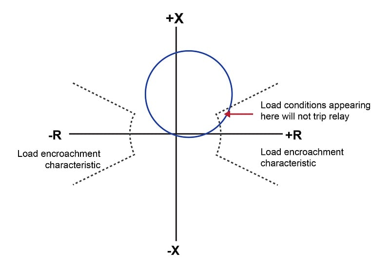
Another common option within digital distance relays is the load encroachment blocking characteristic, designed to prevent relay tripping on heavy (legitimate) loads that might otherwise fall within the reach of the distance relay’s characteristic:
REVIEW:
-
Distance relay technology allows for identification of the fault and its location with respect to the sensing device.
-
Omni-directional distance relaying protects against faults of both forward and reverse power conditions.
-
Directionally-optimized distancing relay designs can be made more sensitive to forward or reverse power with the addition of phase-shifting capacitors.
If you are interested in more content about electrical power control systems, check out these calculators:
Related textbook pages:
- Understanding Electrical Power Grids
- Introduction to Protective Relaying
- Instantaneous and Time-Overcurrent Protection
- Auxiliary and Lockout Relays
Related Technical Articles:
- Understanding Power Quality, Monitoring, and Correction
- Active Power, Reactive Power, Apparent Power, and the Role of Power Factor
- Control and Visualization of Power Plant Data Through SCADA Systems

buen documento