 Facebook
 Google
 GitHub
 Linkedin
Input/Output (I/O) Capabilities of PLCs
How do PLCs handle input and output signals?
Input and output signals are a core component of a PLC’s operation. Discrete DC, discrete AC, and analog are among the most common input and output modules, while the relay is also an extremely common form of output module.
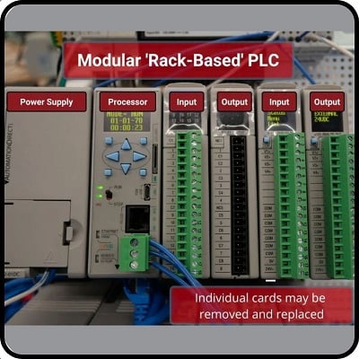
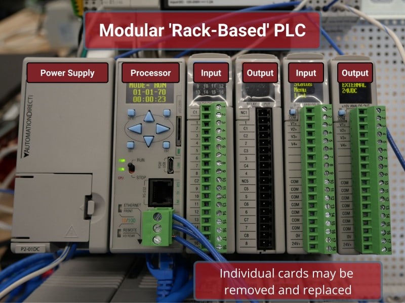
Every programmable logic controller must have some means of receiving and interpreting signals from real-world sensors such as switches and encoders, and also be able to effect control over real-world control elements such as solenoids, valves, and motors. This is generally known as input/output, or I/O, capability. Monolithic (“brick”) PLCs have a fixed amount of I/O capability built into the unit, while modular (“rack”) PLCs use individual circuit board “cards” to provide customized I/O capability.

Monolithic vs Modular PLCs
The advantages of using replaceable I/O cards instead of a monolithic PLC design are numerous. First, and most obvious, is the fact that individual I/O cards may be easily replaced in the event of failure without having to replace the entire PLC. Specific I/O cards may be chosen for custom applications, biasing toward discrete cards for applications using many on/off inputs and outputs, or biasing toward analog cards for applications using many 4-20 mA and similar signals. Some PLCs even offer the feature of hot-swappable cards, meaning each card may be removed and a new one inserted without de-energizing power to the PLC processor and rack.
Please note that one should not assume any system has hot-swappable cards, because if you attempt to change out a card “live” in a system without this feature, you run the risk of damaging the card and/or the rest of the unit into which it is plugged!
Remote I/O Racks
Some PLCs have the ability to connect to processor-less remote racks filled with additional I/O cards or modules, thus providing a way to increase the number of I/O channels beyond the capacity of the base unit. The connection from host PLC to remote I/O racks usually takes the form of a special digital network, which may span a great physical distance:

An alternative scheme for system expansion is to network multiple PLCs together, where each PLC has its own dedicated rack and processor. Through the use of communication instructions, one PLC may be programmed to read data from and/or write data to another PLC, effectively using the other PLC as an extension of its own I/O. Although this method is more expensive than remote I/O (where the remote racks lack their own dedicated processors), it provides the capability of stand-alone control in the event the network connection between PLC processors becomes severed.
Input/output capability for programmable logic controllers comes in three basic varieties: discrete, analog, and network; each type discussed in the following subsection.
Discrete Input Modules
A “discrete” data point is one with only two states on and off. Process switches, pushbutton switches, limit switches, and proximity switches are all examples of discrete sensing devices. In order for a PLC to be aware of a discrete sensor’s state, it must receive a signal from the sensor through a discrete input channel. Inside each discrete input, a module is (typically) a set of light-emitting diodes (LEDs) which will be energized when the corresponding sensing device turns on. Light from each LED shines on a photo-sensitive device such as a phototransistor inside the module, which in turn activates a bit (a single element of digital data) inside the PLC’s memory. This opto-coupled arrangement makes each input channel of a PLC rather rugged, capable of isolating the sensitive computer circuitry of the PLC from transient voltage “spikes” and other electrical phenomena capable of causing damage:

The internal schematic diagram for a discrete input module (“card”) shown above reveals the componentry typical for a single input channel on that card. Each input channel has its own optocoupler, writing to its own unique memory register bit inside the PLC’s memory. Discrete input cards for PLCs typically have 4, 8, 16, or 32 channels.
Discrete Output Modules
Indicator lamps, solenoid valves, and motor starters (assemblies consisting of contactors and overload protection devices) are all examples of discrete control devices. In a manner similar to discrete inputs, a PLC connects to any number of different discrete final control devices through a discrete output channel. Discrete output modules typically use the same form of opto-isolation to allow the PLC’s computer circuitry to send electrical power to loads: the internal PLC circuitry driving an LED which then activates some form of a photosensitive switching device. Alternatively, small electromechanical relays may be used in lieu of opto-isolating semiconductor switching elements such as transistors (DC) or TRIACs (AC):

As with the schematic diagram for a discrete input module shown previously, the schematic diagram shown here for a discrete output module reveals the componentry typical for a single channel on that card. Each output channel has its own optocoupler, driven by its own unique memory register bit inside the PLC’s memory. Discrete output cards for PLCs also typically have 4, 8, 16, or 32 channels.
Source and Sink
An important concept to master when working with DC discrete I/O is the distinction between current-sourcing and current-sinking devices. The terms “sourcing” and “sinking” refer to the direction of current (as denoted by conventional flow notation) into or out of a device’s control wire. A device sending (conventional flow) current out of its control terminal to some other device(s) is said to be sourcing current, while a device accepting (conventional flow) current into its control terminal is said to be sinking current.
To illustrate, the following illustration shows a PLC output channel is sourcing current to an indicator lamp, which is sinking current to the ground:

These terms really only make sense when the electric current is viewed from the perspective of conventional flow, where the positive terminal of the DC power supply is envisioned to be the “source” of the current, with current finding its way “down” to ground (the negative terminal of the DC power supply). In every circuit formed by the output channel of a PLC driving a discrete control device, or by a discrete sensing device driving an input channel on a PLC, one element in the circuit must be sourcing current while the other is sinking current.
An engineering colleague of mine has a charming way to describe sourcing and sinking: blowing and sucking. A device that sources current to another “blows” current toward the other device. A device that sinks current “sucks” current from the other device. Many students seem to find these terms helpful in first mastering the distinction between sourcing and sinking despite (or perhaps because of!) their informal nature.
If the discrete device connecting to the PLC is not polarity-sensitive, either type of PLC I/O module will suffice. For example, the following diagrams show a mechanical limit switch connecting to a sinking PLC input and to a sourcing PLC input:
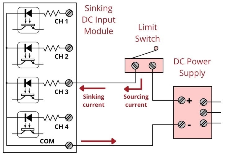

Note the differences in polarity and labeling between the sinking card’s common terminal and the sourcing card’s common terminal. On the “sinking” card, the input channel terminal is positive while the common (“Com”) terminal is negative. On the “sourcing” card, the input channel terminal is negative while the common (“VDC”) terminal is positive.
Some discrete sensing devices are polarity-sensitive, such as electronic proximity sensors containing transistor outputs. A “sourcing” proximity switch can only interface with a “sinking” PLC input channel, and vice-versa:


In all cases, the “sourcing” device sends current out of its signal terminal while the “sinking” device takes current into its signal terminal.
Two photographs of a DC (sinking) discrete input module for an Allen-Bradley model SLC 500 PLC are shown here: one with the plastic cover closed over the connection terminals, and the other with the plastic cover opened up for viewing the terminals. A legend on the inside of the cover shows the purpose of each screw terminal: eight input channels (numbered 0 through 7) and two redundant “DC Com” terminals for the negative pole of the DC power supply to connect:


LED Indicator Lights
A standard feature found on practically every PLC discrete I/O module is a set of LED indicators visually indicating the status of each bit (discrete channel). On the SLC 500 module, the LEDs appear as a cluster of eight numbered squares near the top of the module.
A photograph of discrete output terminals on another brand of PLC (a Koyo model DL06) shows somewhat different labeling:

Here, each output channel terminal is designated with a letter/number code beginning with the letter “Y”. Several “common” terminals labeled with “C” codes service clusters of output channels. In this particular case, each “common” terminal is common only to four output channels. With sixteen total output channels on this PLC, this means there are four different “common” terminals. While this may seem somewhat strange (why not just have one “common” terminal for all sixteen output channels?), it more readily permits different DC power supplies to service different sets of output channels.
AC Discrete I/O Modules
Electrical polarity is not an issue with AC discrete I/O since the polarity of AC reverses periodically anyway. However, there is still the matter of whether the “common” terminal on a discrete PLC module will connect to the neutral (grounded) or hot (ungrounded) AC power conductor.
The next photograph shows a discrete AC output module for an Allen-Bradley SLC 500 PLC, using TRIACs as power switching devices rather than transistors as is customary with DC discrete output modules:

This particular eight-channel module provides two sets of TRIACs for switching power to AC loads, each set of four TRIACs receiving AC power from a “hot” terminal (VAC 1 or VAC 2), the other side of the load device being connected to the “neutral” (grounded) conductor of the AC power source.
Fortunately, the hardware reference manual supplied by the manufacturer of every PLC shows diagrams illustrating how to connect discrete input and output channels to field devices. One should always consult these diagrams before connecting devices to the I/O points of a PLC!
Analog I/O Modules
In the early days of programmable logic controllers, processor speed and memory were too limited to support anything but discrete (on/off) control functions. Consequently, the only I/O capability found on early PLCs were discrete in nature. Modern PLC technology, though, is powerful enough to support the measurement, processing, and output of analog (continuously variable) signals.
All PLCs are digital devices at heart. Thus, in order to interface with an analog sensor or control device, some “translation” is necessary between the analog and digital worlds. Inside every analog input module is an ADC, or Analog-to-Digital Converter, a circuit designed to convert an analog electrical signal into a multi-bit binary word. Conversely, every analog output module contains a DAC, or Digital-to-Analog Converter, a circuit to convert the PLC’s digital command words into analog electrical quantities.
Analog I/O is commonly available for modular PLCs for many different analog signal types, including:
- Voltage (0 to 10 volt, 0 to 5 volt)
- Current (0 to 20 mA, 4 to 20 mA)
- Thermocouple (millivoltage)
- RTD (millivoltage)
- Strain gauge (millivoltage)
The following photographs show two analog I/O cards for an Allen-Bradley SLC 500 modular PLC system, an analog input card, and an analog output card. Labels on the terminal cover doors indicate screw terminal assignments:


Network I/O
Many different digital network standards exist for PLCs to communicate with, from PLC to PLC and between PLCs and field devices. One of the earliest digital protocols developed for PLC communication was Modbus, originally for the Modicon brand of PLC. Modbus was adopted by other PLC and industrial device manufacturers as a de facto standard and remains perhaps the most universal digital protocol available for industrial digital devices today.
Another digital network standard developed by a particular manufacturer and later adopted as a de facto standard is Profibus, originally developed by Siemens.
For more information on networking standards used in PLC systems, refer to the “Digital electronic instrumentation” chapter, specifically sections on specific network standards such as Modbus and Profibus.
REVIEW:
-
Discrete inputs allow connection of sensors, switches, and button; they can be either AC or DC voltage types.
-
Discrete outputs may be DC, AC, or relay, allowing connections to coils, lights, and audible signals.
-
Both DC input and DC output modules can be of sourcing or sinking variety, referring to the direction of current flow.
-
Analog inputs and outputs receive and send variable voltage and current signals.
Interested in more PLC content?
Related Videos:
Textbook Pages:
Tutorials and Technical Articles:
- Ladder Logic in Programmable Logic Controllers (PLCs)
- Intro to PLC Programming with Rockwell’s Studio 5000 and CompactLogix
- Intro to Siemens S7-1200 PLC and TIA Portal Programming
- Understanding PLC Program Commands: Timers
