 Facebook
 Google
 GitHub
 Linkedin
Interconnected Generators

What Is Generator Interconnection in Electrical Power Systems?
All parallel-connected generators must output the same voltage to the grid in order to share the load. Additionally, AC generators must closely match output voltage at every point along their sine-wave cycles. Synchronizing voltage and frequency ensures reliability and equally shared operation.
Any power grid large enough to meet the demand of an entire nation must have multiple generators drawing from multiple energy sources supplying that power. Connecting these generators together so as to equitably share loads in the grid is no trivial task. The basic concepts involved with interconnecting generators, however, are independent of the distance separating those generators. Thus, the examples given in this section are as relevant to generators located adjacent to each other as they are to generators located hundreds of miles apart.
Parallel DC Generators
Let’s begin with a simple electromechanical DC generator application, where one generator supplies power to one load. Although not shown in this electrical schematic, there will be some form of “prime mover” such as an engine or a turbine turning the mechanical shaft of the generator:

This system is almost too simple to warrant comment: the generator outputs a constant voltage, with load current being a function of load resistance in accordance with Ohm’s Law (\(I = {V \over R}\)). If load resistance happens to decrease and generator voltage remains constant, the load current will increase as a result. This additional load current has the effect of making the electromechanical generator harder to turn at the same shaft speed: demanding greater mechanical power input to the generator in order to deliver greater electrical power to the load. In this way the generator naturally “senses” the power demanded by the load.
Now, let us consider a second generator added in parallel to this simple power “grid”. In this configuration each of the two generators should contribute current to the grid, helping each other power the one load (resistor) shown on the right-hand side of the diagram:
We know from basic circuit theory that parallel-connected components share the same voltage. From this principle, we may conclude that the two generators \(V_1\) and \(V_2\) will need to output the same amount of voltage in order to be compatible with each other in this circuit configuration. To further explore this concept, we will consider what would happen if the two generator voltages were unequal to each other, including the resistance of the line connecting the two generators together:

If the voltage of generator \(V_1\) exceeds the voltage of generator \(V_2\), the difference of those two generators’ output voltages will be dropped along the length of the conductor \(R_{line}\). Ohm’s Law allows us to predict the amount of current flowing through that line arising from the generators’ differing output voltages (\(I = {{V_1 - V_2} \over R_{line}}\)). If the voltage difference is substantial and the line resistance is minimal, this current will be quite large. If this amount of current exceeds the amount drawn by the load, Kirchhoff’s Current Law tells us the current through generator \(V_2\) will be going the wrong direction: down rather than up.
This situation is undesirable because it means generator \(V_2\) will actually be functioning as a load rather than as the source it should be. Not only will generator \(V_2\) not be contributing any power to the grid, but it will actually draw power away from generator \(V_1\) that could otherwise go to the load. If generator \(V_2\) is an electromechanical machine, it will operate as a motor as it draws power from generator \(V_1\): “motor” \(V_2\) increasing speed and generator \(V_1\) slowing down from the additional loading.
To summarize: parallel-connected DC generators must output the same voltage in order to equitably share the burden of powering loads. If one generator outputs less voltage than another, it will contribute less power. if this disparity is great enough, the weaker generator will actually become a load and begin to function as an electric motor rather than the generator (source) it should be.
Parallel AC Generators
Connecting AC generators in a power grid presents the same fundamental problem: all parallel-connected generators must output the same voltage to the “grid” in order to equitably share the load. What makes AC generator interconnections more complex than DC generator interconnections is the fact that the voltage output by an AC generator is not a static quantity but rather is oscillating sinusoidally. This means paralleled AC generators must closely match one another’s output voltage at every point along their sine-wave cycles in order for them to productively work together on the grid. The only way two or more AC generators may continuously match one another’s output voltage is if their peak voltages are the same, their frequencies are the same, and they remain in-phase with each other.
AC generator frequency is a direct function of shaft speed. AC generator voltage is a direct function of shaft speed and rotor excitation current. Thus, in order to connect two or more AC generators together, these two parameters must be precisely controlled.
The process of ensuring an AC generator is ready to be connected to a live grid is called synchronization. This may be done manually by human operators, or automatically by synchronization relays. However it is done, the principle is the same: the voltage output by the un-synchronized generator is compared against the voltage of the grid, and the disconnecting switch or circuit breaker is not closed until the difference between those two voltages is nearly zero.
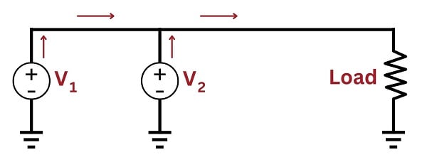
A simplified demonstration circuit serves to illustrate this process:

Imagine a condition where generator \(V_1\) is operating and powering the load, but generator \(V_2\) is stopped with its disconnecting switch in the open position. In this condition the lamp will glow steadily, operating on the difference of potential between the power line (full AC voltage) and the idle generator \(V_2\) (0 volts).
AC Generators with Different Frequencies
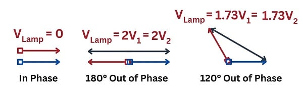
If we bring generator \(V_2\) up to speed while keeping the disconnect switch in its open position, regulating the generator \(V_2\)’s output voltage and frequency to be equal to generator \(V_1\), the lamp will experience a voltage strictly dependent on the degree of phase shift between the two generators. If at this correct voltage and frequency, the phase of generator \(V_2\) precisely matches the phase of generator \(V_1\) (i.e. the sine-wave outputs of these two generators are in perfect lock-step with each other), the lamp will experience zero voltage and will remain dark. If the two generators happen to be exactly 180 degrees out of phase with each other while maintaining equal voltage and frequency, the lamp will experience a sinusoidal voltage at that same frequency having a peak value twice that of either generator and will, therefore, glow at maximum brightness. If the amount of phase shift between these two generators is any value between 0\(^{o}\) and 180\(^{o}\), the voltage experienced by the lamp will vary proportionately.
If you imagine the two generators’ voltages being phasors joined at the tails, the amount of voltage seen by the lamp will be equivalent to the distance between those two phasors’ tips:
If the two generators output different frequencies, the phase shift angle between them will not be constant. Instead, the two generators will fall in and out of phase with each other at a frequency equal to the difference between the individual generator frequencies. For example, if \(V_1\) outputs 240 volts peak at 60 Hz and \(V_2\) outputs 240 volts peak at 59 Hz, the two generators will roll in and out of phase with each other once per second (60 Hz \(-\) 59 Hz = 1 Hz). The lamp will thus experience an AC voltage that varies from 0 volts (when the two generators happen to be perfectly in phase) to 480 volts peak (when the two generators happen to be 180\(^{o}\) out of phase). In visual terms, this means the lamp will alternate from complete darkness to full brightness and back again once per second. Thus, the lamp’s oscillation serves to indicate the difference in frequencies between the two generators.
If the two generators output different amounts of voltage and at different frequencies, the lamp will oscillate from bright to dim, never reaching full brightness or going completely dark. Thus, the amount of variance in lamp intensity serves to indicate the difference in voltage between the two generators.
The purpose of the lamp in this circuit, of course, is to indicate when it is safe to close the disconnect switch and tie generator \(V_2\) to the power grid. Since we know paralleled generators are electrically compatible only when their output voltages match at all times, we look for a condition of complete lamp darkness before closing the disconnect switch.
AC Generators with Synchronized Frequencies
Once the generators have been synchronized and the disconnect switch closed, an interesting phenomenon occurs: the two generators now behave as if their shafts were mechanically coupled together. This is similar to the phenomenon experienced with the two parallel-connected DC generators shown earlier, where an under-performing generator would begin to “motor” and draw power from the stronger generator if their voltages were sufficiently different. In the case of paralleled AC generators, a generator that begins to lag behind the other(s) in speed will act as a synchronous motor and draw power from the grid to match the speed of the other generator(s), staying in lock-step with the grid frequency so long as it is connected to the grid.
If an AC generator is synchronized and connected to the grid, and then its prime mover’s power is increased in an attempt to increase the shaft speed, that generator will in effect be trying to force all the other AC generators on that grid to a faster speed. If the generator in question represents a small fraction of the grid’s total power generating capacity as is typically the case, increasing or decreasing its speed becomes impossible due to this coupling effect.
REVIEW:
-
DC Generators in parallel must have the same voltage or else the higher-voltage generator will drive current in reverse through the lower-voltage generator.
-
Two AC generators must have not only the same voltage, but the same rotation frequency or else the loads will periodically experience oscillation between 0 volts and the sum of the two individual voltages.
-
When two AC generators are engaged electrically at a consistent frequency, the rotation speed of the motors are now electrically interlocked together, as if mechanically.
If you are interested in more content about electrical power control systems, check out these calculators:
Related textbook pages:
- Understanding Electrical Power Grids
- Introduction to Protective Relaying
- Instantaneous and Time-Overcurrent Protection
- Auxiliary and Lockout Relays
Related Technical Articles:
- Understanding Power Quality, Monitoring, and Correction
- Active Power, Reactive Power, Apparent Power, and the Role of Power Factor
- Control and Visualization of Power Plant Data Through SCADA Systems
