Motor 2x Frequency

Dear all,

We have the following motor at our site:
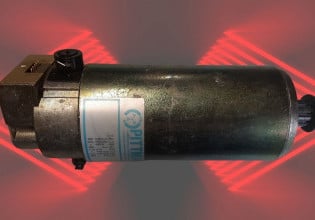
HP-60, V-400, RPM-2960, A-79.4, Delta, PF-0.88, Insul. Class F. It is a frame 225M Siemens Motor, manufactured in 1998.

The motor was recently checked by MTS and they say that:

*QUOTE*

"Vibration data was acquired for the subject machine. Vibration amplitudes on motor were recorded as high 0.59 in/s which is beyond critical limits therefore machine can’t be allowed to operate in such condition. Motor Issues need to be addressed , kindly shutdown the machine .

Please note that the motor issue resulting in Line frequency had already been highlighted. Since this frequency lies in close proximity to mechanically induced 2x frequency , it is resulting in beating and therefore overshooting of vibration amplitudes.

MP-723 B - Fire water Pump B (25-Aug-20) PARM = OVERALL

MOH=Motor Outboard Horizontal .218 .219 In/Sec -.0017 -1
MOP=Motor Outboard Horz Peakvue .107 .120 G-s -.012 -10
MOV=Motor Outboard Vertical .201 .166 In/Sec .036 21
MIH=Motor Inboard Horizontal .205 .162 In/Sec .043 27
MIP=Motor Inboard Horz Peakvue .064 .201 G-s -.137 -68
MIV=Motor Inboard Vertical .519 .473 In/Sec .046 10 #
MIA=Motor Inboard Axial .592 .542 In/Sec .050 9 #
PIH=Pump Inboard Horizontal .109 .096 In/Sec .013 14
PIV=Pump Inboard Vertical .163 .125 In/Sec .037 30
PIA=Pump Inboard Axial .122 .097 In/Sec .025 26
POH=Pump Outboard Horizontal .150 .169 In/Sec -.019 -11
POP=Pump Outboard Horz Peakvue 1.571 2.168 G-s -.596 -28
POV=Pump Outboard Vertical .139 .204 In/Sec -.065 -32
POA=Pump Outboard Axial .130 .085 In/Sec .044 52 %


  • 2x & 2.02 ( Line frequency ) are both evident in spectrums .
  • Presence of line frequency has been confirmed via coast down data . As soon as machine is shutdown this specific peak vanishes confirming its relation with electromagnetism.
  • 2xLF is also observed when motor is run in uncoupled condition in the field.
  • Line frequency in conjunction with 2x peak might be resulting in beating and therefore high amplitudes.
  • There can only be two reasons for Line frequency . Either soft foot or issues with motor stator / rotor.
  • FM team has verified absence of soft foot."

*UNQUOTE*

What do you guys think about the attached frequency spectrum?
What the the checks we can do at shop to verify that the fault is electrical in nature? to be specific how can we test the rotor at shop for health of bars?

Regards,
Mutahir
 

Attachments

Dear all,

We have the following motor at our site:
HP-60, V-400, RPM-2960, A-79.4, Delta, PF-0.88, Insul. Class F. It is a frame 225M Siemens Motor, manufactured in 1998.

The motor was recently checked by MTS and they say that:

*QUOTE*

"Vibration data was acquired for the subject machine. Vibration amplitudes on motor were recorded as high 0.59 in/s which is beyond critical limits therefore machine can’t be allowed to operate in such condition. Motor Issues need to be addressed , kindly shutdown the machine .

Please note that the motor issue resulting in Line frequency had already been highlighted. Since this frequency lies in close proximity to mechanically induced 2x frequency , it is resulting in beating and therefore overshooting of vibration amplitudes.

MP-723 B - Fire water Pump B (25-Aug-20) PARM = OVERALL

MOH=Motor Outboard Horizontal .218 .219 In/Sec -.0017 -1
MOP=Motor Outboard Horz Peakvue .107 .120 G-s -.012 -10
MOV=Motor Outboard Vertical .201 .166 In/Sec .036 21
MIH=Motor Inboard Horizontal .205 .162 In/Sec .043 27
MIP=Motor Inboard Horz Peakvue .064 .201 G-s -.137 -68
MIV=Motor Inboard Vertical .519 .473 In/Sec .046 10 #
MIA=Motor Inboard Axial .592 .542 In/Sec .050 9 #
PIH=Pump Inboard Horizontal .109 .096 In/Sec .013 14
PIV=Pump Inboard Vertical .163 .125 In/Sec .037 30
PIA=Pump Inboard Axial .122 .097 In/Sec .025 26
POH=Pump Outboard Horizontal .150 .169 In/Sec -.019 -11
POP=Pump Outboard Horz Peakvue 1.571 2.168 G-s -.596 -28
POV=Pump Outboard Vertical .139 .204 In/Sec -.065 -32
POA=Pump Outboard Axial .130 .085 In/Sec .044 52 %


  • 2x & 2.02 ( Line frequency ) are both evident in spectrums .
  • Presence of line frequency has been confirmed via coast down data . As soon as machine is shutdown this specific peak vanishes confirming its relation with electromagnetism.
  • 2xLF is also observed when motor is run in uncoupled condition in the field.
  • Line frequency in conjunction with 2x peak might be resulting in beating and therefore high amplitudes.
  • There can only be two reasons for Line frequency . Either soft foot or issues with motor stator / rotor.
  • FM team has verified absence of soft foot."

*UNQUOTE*

What do you guys think about the attached frequency spectrum?
What the the checks we can do at shop to verify that the fault is electrical in nature? to be specific how can we test the rotor at shop for health of bars?

Regards,
Mutahir
Mutahir,

As per the informations that you provided, we can think about a misalignement ...and in other hand can be another source of vibrations... & you stated that soft foot can be eliminated .

Did you ever perform a realignement and checked results ?

Do you know critical speed of the motor when vibrations spikes?

Is that motor equipped with VSD,,?

You may have also to perform resonance natural frequency test on this equipment ...

Check on the web there are good informations on Such tests and vibration analysis for multistage motorpump..

Check these notes from a case study :
Vibration in a Multistage Centrifugal Pump under Varied Conditions
Abstract
Multistage pumps are intended to improve designs with low-vibration and -noise features as the industry applications increase the technical requirements. In this frame, it becomes really important to fully understand the vibration patterns of these kinds of complex machines. In this study, a vibration test bench was established to examine the vibration and stability of a cantilever multistage centrifugal pump under different flow rates. The vibration spectrum diagrams for the inlet and outlet sections and the pump body were evaluated under varied flow conditions. Results showed the effects of operational conditions on the vibration of the cantilever multistage centrifugal pump. Vibration velocity was primarily caused by mass unbalance at the shut-off flow rate point. Under different flow conditions, the blade passing frequency (BPF) and two times the blade passing frequency (2BPF) were the main excitation frequencies. The vibration frequency of the final pump body remained at the BPF under different flow conditions due to the contact with the outlet section. The major type of vibration frequency for the inlet and outlet was high frequency.

...........
.......
4. Conclusion
The vibration state of a cantilever multistage centrifugal pump has been measured and analyzed for different flow rates in this study. The results showed that the flow rates exerted distinct effects on the vibration spectrum at the inlet and outlet sections of the cantilever multistage centrifugal pump. The amplitudes of the vibration velocity were larger under the extreme flow conditions (i.e., 0Qdes and 1.5Qdes). The dominant frequencies at different stages could change with the operation conditions. The dominant frequency for the first and last stages was the BPF at the shut-off flow rate point, and the dominant frequency of other stages was 2BPF. The variation in the vibration dominant frequency at the overloading flow rates was similar to that at the design flow rate. The dominant frequency of the last-stage pump body was the BPF under different flow rate conditions because the last-stage diffuser vanes were connected with the outlet section. The main vibration frequency range of the cantilever multistage centrifugal pump was found to be in the range of one to four times the BPF and likely to be one or two times the blade frequency. Mass unbalance primarily accounted for the vibration at the shut-off flow rate point. However, pump vibration was mainly caused by the pressure pulsation at the design and overloading flow rates.

The presented results could enrich the known database for optimization purposes. The domain frequency relates to the BPF, and the vibration frequency concentrates at the low-frequency range; hence, the vibration by the arrangement of impeller blades among stages can be reduced or controlled. The whole study confirms the validity and potential for future research works on the topic of the stage coupling vibration.

Here some others quotes from another case study:
CONCLUSION
From the Vibration Signature we observe that
multiple sub harmonics are present and it can also be seen
that harmonics peaks are decreasing in amplitude form the
first dominant peak which is 2.5*N. In vertical position
vibration spectrum 2*N peak is seen as dominant peak.
Thus, analysis of the entire three vibration spectrum clearly
depicts the patterns of Mechanical Looseness. Loose
mounting bolts will also cause mechanical looseness. Cracks
in base frame or bearing house will also accounts for
mechanical looseness. Upon investigation loose mounting
bolts are found and corrected.
FUTURE WORK
Mechanical looseness may also occur due to
excessive clearance. As an assembly setup certain amount
of clearance is provided for rotor components. Clearance is
provided as per the diameter of rotor component. These
clearance values are to be rechecked and possibility of
reduction in vibration by varying the clearance values is to
be investigated in future.

How about flow rate? Is that vibrations occur at differents or only one flow rate?

ControlsGuy25.
 
MRasool.
The data are inconsistent or lacking:
1) Nameplate data reveals motor's rated RPM is 2,960 resulting in a full-load slip of 40 rpm (1.33 %). Charts 2, 5, and 8, indicate slip of 25 rpm (0.0083 % at 100% load) ! If true, then motor is not 100 % loaded !
2) Where are the corroborating electrical parameters, i.e., 3-Phase Volts, Amps, Power ?
3) I also agree with ControlsGuy25's question related to the hydraulic parameters, i.e., flow-rate (Q) and head (H)!
4) Where are the vibration data related to connected piping structure?
5) Where are the vibration data related to the pump/motor foundation?
6) Where are the Ambient temperature and environmental conditions ?
Regards, Phil Corso
 
Thank you for your comments.

Here is what we did:

We brought the motor to the shop and made a temporary fixed foundation. We got MTS to make their spectrum reading in this case. Previously there was no fixed foundation and I assume that was contributing to the vibration.

MTS made following comments:

*QUOTE*


Solo run of the subject motor has been conducted in workshop with makeshift bolting arrangement , on FM’s reservation another data-set was acquired with coupling hub installed . In both instances the problematic line frequency was not observed . Therefore it points towards skid unevenness / soft foot issue resulting in uneven stator-rotor air gap and therefore the line frequency . Based on these observation following way forward is recommended


  • Ensure evenness / proper leveling of the skid
  • Eliminate motor soft-foot ( avoid using more than 2 shims )
  • Solo-run to be conducted before coupling
  • Ensure proper alignment ( less than 0.003” )


MP-723 B - Fire water Pump B (28-Aug-20) PARM = OVERALL

MOH=Motor Outboard Horizontal .044 .099 In/Sec -.054 -55

MOP=Motor Outboard Horz Peakvue .285 .279 G-s .0060 2

MOV=Motor Outboard Vertical .089 .053 In/Sec .035 66 %

MIH=Motor Inboard Horizontal .053 .096 In/Sec -.043 -45

MIP=Motor Inboard Horz Peakvue .225 .251 G-s -.026 -10

MIV=Motor Inboard Vertical .035 .093 In/Sec -.058 -63

MIA=Motor Inboard Axial .088 .066 In/Sec .022 33


*UNQUOTE*


For now, FM is reinforcing the foundation.

Regards,
Mutahir
 
2x applied frequency on a 2 pole motor such as this is often associated with a broker rotor bar., because the broken bar will pass through each pole once per revolution, so with 2 poles it results in 2x the frequency.

There is a test system called a "growler" that can be used to detect it. They can be bought or fabricated, but it involves removing the rotor and placing it in a cradle. Typically this is something that a motor shop can do, because it's expensive to built the test equipment for a one-off use.
 
A simple method to confirm a suspected broken-bar is the problem is to hold a de-tuned portable AM radio close to the operating motor . It will "crackle" at slip frequency ! Also use forum's search feature for Post # 1026165830
Phil Corso
 
[U]mnewiraq[/U]...
At no-load an induction motor (squirrel cage) runs at practically synchronous speed; at full-load its speed is below synchronous speed by a percentage known as slip-frequency ! For example, if the synchronous speed is 1,500 rpm and full-load speed is 1,410 rpm, then slip-frequency at full-load is 90/1,500 or 6.0% !

A failure in the motor rotor's construction will most likely involve the connection between the rotor bar(s) and their shorting-ring(s), resulting in open-circuits, hence arcing-current !

The greater the fault, the greater the effect, but the best indicator will be noise in the rotor. If minor it can't be heard by the human ear, if major, it could sound like a growl ! But, since current-arcing always occurs at slip-frequency, it can be heard at radio frequencies. In closing, the next paragraph is what one Forum member experienced.

" Phil Corso suggested that I put up this information along with the successful application of his broken rotor-bar test. An AM radio was tuned to a dead part of the band and the antenna placed 1 inch from the motor case. Indeed, when near motor rpm was reached, a crackle could be heard every second or two, indicating arcing in a rotor bar. The crackle disappeared when the motor went off line."

Regards, Phil Corso
 
mnewirag...
Following is a 1/03/2003 response to a member of the Control.com forum:
"I want to make it clear that my mechanical vibration expertise is limited. I usually get involved when all mechanical vibration causes are exhausted. Vibration due to mechanical failures is quite varied and you should contact a good vibration analysis company such as Bentley-Nevada! I will confine my comments to those vibrations that are the most prevalent due to electrical failures.

Vibration or noise caused by electrical failures are usually related to slip-speed. It occurs mostly in large or higher voltage motors ! It's caused when the rotor-bar separates from the end-ring because of a poor bar-to-ring joint, caused by excessive acceleration time, frequent starts without adequate cooling periods between starts, low acceleration torque (motor-torque minus load-torque), ignorance of rotating inertia (WK^2 or GD^2) effects, or a combination, thereof. Believe it or not, some engineers forget how to convert WK^2 to GD^2 or vice-versa, or can't express load-inertia in terms of motor speed (But that's another story) !

Sometimes the vibration is highest at start, then reduces as the motor accelerates. This occurs because the slip-speed or frequency and subsequent rotor-current is highest at start, then gradually reduces as the motor approaches rated speed.

I also want to emphasize that, in my experience, most motor-rotor failures are the result of inadequate attention paid to starting requirements. "

Anyone interested in the investigation of random tripping of a 14,000 Hp motor ? It took 5 weeks and involved experts from different engineering fields plus a psychologist ! When the cause was determined no-one believed it !

Regards, Phil Corso
 
Top