Gain and Bias on PV and STPT on a PID controller [Ovation DCS]

Hi everyone, i found this forum looking for information about how to set Gain and Bias parameters in a PID controller. I know the theory of how this controller works, but looking in the control sheets in DCS (Ovation) its hard for me to understad the parameters configurated. Here is an example:
  • PV range: -100 to 100
  • SP range: 0 to 100
  • PVGain: 0,12
  • PVBias: 0
  • SPTG: 0,12
  • SPTB: 0
  • TPSC=18
  • BTSC= -15
For what i read on the Ovation online help, GAIN & BIAS are used to normalize the process or SP variable to a 0 to 100 % value, but in the example above i can't understand how they did it.
Regards and thanks a lot for your time.
 
Those Gain and Bias fields aren't tuning parameters they're a straight linear scale (percent = EU × Gain + Bias) that maps your PV and SP onto the common 0–100% span the algorithm actually does its math on. So the real question isn't PID at all, it is generally what two numbers put my point's range onto 0–100%. For a point that should read 0% at the bottom of range and 100% at the top: Gain = 100 / (high range − low range), and Bias = −(low range) × Gain. If you run that against your own endpoints as a check, plug the low and high of the PV range into EU × Gain + Bias, you should land exactly on 0 and 100.

Here's one simple thing to think it better, a PV range of −100 to 100 does not produce Gain 0.12 / Bias 0. That pair maps a zero-based point running to about 833 EU full scale (100 / 0.12), whereas −100…+100 would need roughly Gain 0.5 / Bias 50. So before working the example, pull the point record and confirm the engineering range the transmitter is actually scaled to, I'd 100% bet the −100 to 100 what you mentioned is not the range the algorithm is seeing.

Same exercise on SPTG/SPTB for the setpoint.

One more important thing is to confirm the direction of the scale on your algorithm sheet, if your revision applies it as percent = (EU − Bias) × Gain, the sign on Bias flips, so trust the endpoint check over any formula.
 
I’d add one qualification to the previous reply: PV and SP need to represent the same physical value on the same internal scale. A restricted setpoint range doesn’t necessarily require a different normalisation.

Assuming the block uses scaled = input × gain + bias, your current settings give:

Input
Scaled value with gain 0.12, bias 0​
−100
−12​
0
0​
100
12​
So those settings don’t map −100…100 to 0…100. However, that alone doesn’t establish that the configuration is wrong; we need to know what values actually reach the block and what scaling the application intends.

For example, mapping −100…100 to 0…100 requires 0.5 × input + 50. If PV and SP arrive in the same engineering units, that transformation should apply to both. An allowed SP range of 0…100 would then occupy 50…100% internally. Independently mapping SP to 0…100% would create a false error: PV = SP = 50 would become PV = 75% and SP = 50%.

If the PV originates from a 4–20 mA transmitter, trace the earlier conversions too. This pressure-transmitter documentation illustrates configurable transmitter zero/span, while this current-loop receiver example illustrates the receiving hardware. Those provide background on stages upstream of the PID calculation.

Could you share the exact Ovation algorithm name/revision, its scaling equation, and which point the TPSC/BTSC fields belong to? That would help distinguish input scaling, permitted setpoint limits and output limits before suggesting replacement values.
 
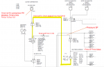
First thing first...thanks a lot for taking your time to answer this question. I've been reading a lot of documentation and your answers to have more knowledge about this. I work as a power plant control room and its so hard to practice this functions. I attached a picture with the control sheet of this PID, with some notes. As you can see, the PV value is not coming straight from a sensor, its the combination of two function output, both calculating the deviation from main steam pressure and power deviation, and this value its being compared to 0 error.
Notes on PID.png
Notes on PID.png
 
Top