GE Mark V <R> reaches A7 although it displays at reset IO CFG failed

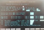
I went back and looked at the Voting Mismatch spreadsheet that was prepared before the TCDA in Loc. 3 of <QD1> was replaced, and I see SFL2 was also not being voted "properly"--but again, I believe that signal is derived from the SVL PT input signal, so if <Z> isn't seeing SVL then it's going to think SFL2 is 0.00.

I am extremely curious to see another spreadsheet with Pre-Vote voting mismatches AFTER the TCDA in Loc. 3 of <QD1> was changed--both at zero speed AND while running.

I would also be interested to know if <S> is rebooting by itself now, or if that problem has been resolved.

There are Mark* V card suppliers that are replacing the known-to-fail components on TCPS cards and providing them instead of just sending out "tested" TCPS cards with components that may be failing or may have actually failed (again, we're talking about cards that might be 20 years old, or more).

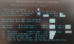
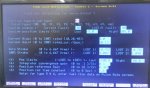
Anyway, I just wanted to say I went back and looked at the spreadsheet and saw SFL2 was not being voted properly by <T>. And, I'm confused more now because we don't know if DV is reading correctly or not.

I have to remind others--and sometimes myself--that Pre-Vote data values are just that: Pre-Vote Values. SOME signals (considered to be critical signals like liquid fuel flow divider feedback and CPD and P2 pressure are actually NOT voted because these signals are deemed critical so each processor uses its "own" values for these signals (sometimes, as with CPD and P2 pressure, there are three, redundant transmitters; liquid fuel flow divider feedback is always three, redundant speed pick-ups; if I recall correctly, synchronizing signals, like DV and SVL are single inputs "fanned out" to all three control processors AND to the three TCEA cards (because the TCEA cards provide critical synchronization check functions) so they aren't voted--but I don't have my notes to look that up at the present moment.
 
Hello everyone,
I lately had impediments to work on the Mark V.
The processor <S> no longer reboot by itself. The problem has been resolved by replacing TCPS.
The <T> processor correctly votes all inputs, even SVL and SFL2. We found the JDT plug of TCTG Loc 4 <P> reversed.
Currently we only have diagnostic alarms in the attachment file.
Thanks to everyone who helped resolve this issue.
 

Attachments

Thank you very much for the feedback, AHNIN! And, congratulations!!!

You didn't say if the unit has been started and synchronized and if the tripping problem has been resolved. The red "trace" conductor of the ribbon cables goes toward the number 1 of the connector it is being plugged into (it is silkscreened on the card at one end or the other of the receptacle on the card). This goes for EVERY cable in the Mark* V.

As for the remaining <T> servo current Diagnostic Alarms, SVO3 is for the liquid fuel bypass valve, and SVO5 is for the IGVs. Something is amiss with the regulator or LVDT feedback--OR the <T> coil of the servo valves (hard to believe that it would be bad for BOTH servos)--OR the TCQA or TCQC of <T>. I think there might otherwise be a problem with LVDT excitation. Remember, the two LVDTs for a particular servo-operated device (in this case the liquid fuel bypass valve or the IGVs) MUST be powered (excited) by different processors, and I believe that LVDT excitation power comes from the QTBA card of each control processor.

The IOMA power supply alarms might be able to dealt with by adjusting the pots as @White suggested. Or, as suggested try another TCPS--one that is known to have new components installed to replace components which have been found to fail long before others. They might be more expensive, but considering the cost of unavailability and no electrical production they would probably be money well spent.

But, without knowing if these alarms are at zero speed or when the unit is running it's difficult to say much more.
 
From Help-QD:

1742 ;TCEA Power supply out of limits, P335
1614 ;TCEA Power supply out of limits, P335
1486 ;TCEA Power supply out of limits, P335

CAUSE The TCEA P335 is out of limits .

EFFECT This is the flame detector supply; it is diode selected on the
trip board TCT_; The loss one P335 supply should not cause a problem.

ACTION Replace TCEA.


The loss of one flame detection should not cause a problem, the loss of two would result in a vote of no flame. You're getting that thing tuned up pretty good, but there are still some issues. These are the things that build up over time and now the unit is tripping all the time again. Good find on the JDT ribbon.

These few alarms might not look like much compared to where you started, but don't take your eye off of them.
 
Hello! and thank you for the help,
I tried in vain to get the turbine to start and run under load. So, we had no start after replacing the cards... (last start-up since one month). As I have already said, these turbines serve as backup to the network and therefore they are rarely called upon at start-up.
Also I inform you that: 65FP is connected to <R> and <S> and disconnected from <T>. 90TV is only connected to <R> and not connected to <S> and <T>. This was done several years ago due to pumping of the fuel flow and the IGV position.
greetings
 
I'm shocked it ran at all--before the work you have done!!!

Re- connect the servo-valves as they should be connected.

And try to start again.

If you don't obtain a READY TO START indication then you need to be able to tell us what the Process Alarm(s) are that are preventing a START from being initiated. (Most operator interfaces had a rudimentary Start Check (and Trip) display that could be helpful in determining what is causing the issue with starting (or tripping).

This is just getting worse and worse, instead of better and better. It's abominable, is what it is.

I presume by "pumping" you are referring to oscillations of the IGVs and LFBV (liquid fuel bypass valve) during starting and operation. I also presume that some logic signals were forced to permit a START.

To me, this is sickening. We just keep getting these dribs and drabs of this is wrong; that is wrong; and both were wrong ALL the effing time.

It would seem you have "inherited" a bag of shite--a big stinking bag of shite.

Let this be a lesson to you: When asking for help on an anonymous World Wide Web forum, from the beginning list all of the issues which affect this machine--including ANY you think might not be applicable. If you didn't need help resolving the problemS you wouldn't have posted here, so give us a clue as to what all the problems are. WE AREN'T THERE AND WE CAN'T SEE OR KNOW WHAT YOU KNOW--UNLESS YOU TELL US.

I wish I could say--and mean--I'm done with this thread. But honestly, I have too much time and effort invested in it to throw in the towel now (no matter how much I want--and I really, Really, REALLY want to throw in the towel). I'm going to have to think about this. It's a true WTF? moment, isn't it?

That was a rhetorical question.

(Google WTF. If you haven't already.)
 
Hi
WTF it's true it's a mess. This is the first time that I have been responsible for working on this turbine and little by little I am discovering the situation and the anomalies. I'm sorry for the time you spent here, but your help was very helpful and I'm happy to have resolved the issues: restarting <S>, incorrect voting of <T>, missing value SVL on <T> and missing CPD value on <R>. According to the title of this debate, the problem is resolved, but moving forward other problems appeared.
Maybe I should have closed this debate and opened a new one dealing with the other problems.
This turbine worked well and without forcing signals despite the disconnection of certain coils of the IGV and LFBV servovalves..
Thank you for understanding.
 
AHNIN,

It's okay; after more than 40 years of this I should be accustomed to it. (But it still frustrates and sometimes infuriates me.)

Based on my knowledge of the Mark* V I cannot understand how the machine could even be started with one control processor intermittently rebooting itself, and a second having so many Voting Mismatch Diagnostic Alarms. You had to be the luckiest person on earth when trying to START that machine because ALL PROCESSORS (Control and Communicator (<C>)) have to up and running to be able to start the machine. Yes, there is SIFT (Software-Implemented Fault Tolerance) and hardware voting (of the servos and <QD1> discrete (contact) outputs. And, all it takes is for all four processors to be up and communicating with each other when a START is initiated for the machine to actually start and run. One control processor could be lost immediately after the unit breaks away from zero speed and it would still continue to accelerate.

But in my experience and understanding of the Mark* V if two servo coils of one servo-operated device are disconnected that would be enough to prevent a START (unless someone had put a 1k ohm resistor across the servo-output terminals of the processor to fool it into thinking it was actually connected to servo coils). Usually there is logic on the TCQA that sees open circuited servo outputs and when two or more are open (on a TMR panel) it won't allow a START (L3ACS logic gets activated if I recall correctly--and the servo regulators will be shorted (at least on the fuel control valves; not on the IGVs).

So, either you aren't describing in terms I recognize or there's more to the story than you know.

I'm still interested to know what happens when you reconnect all the servo coils back to the Mark* V servo outputs and try to initiate a start.

But, if everything you say is true (and it probably is--at the least) then it's a true testament to how well the concept of SIFT was designed and implemented. This would NEVER have happened (STARTing a machine with so many problems on multiple control processors) on a Mark* IV--and it was GE's first TMR control panel that was touted to be so robust. (It was, in many ways, very robust--but when it came to voting signals it was, for the most part, a bust). One processor could think the turbine should be tripped for low-low L.O. pressure and a second processor could think the unit should be tripped for high-high L.O. temperature and the unit would be tripped--with NO PROCESS alarm to indicate why it tripped, because it took two of the three control processors to agree that an alarm condition had been detected before an alarm would be annunciated (an attempt to prevent nuisance alarms...).

I'll continue to help if I can, but this is one for the record books. Ribbon cables plugged in backwards; TCPS card issues (multiple TCPS cards), TCDA issues, ribbon cables disconnected, servo coils disconnected--and the unit still STARTed and ran.

Until it didn't.

Please continue to let us know what happens when the servo coils are reconnected (and a servo polarity check is done on EVERY individual servo coil!!!) and the unit is re-STARTed and synchronized and loaded.

If there are problems, we need to know what Process Alarms AND Diagnostic Alarms are annunciated--as well as what Start-Check Permissives are not true (look at the L3STCK rungs!).

You're almost there!

Well, actually you are there; we aren't.
;)
I learned something. Sure you can misalign the pins on something like the 3PL cable, but how do you reverse a JDT? Yes pin 1 is red, but doesn't the ribbon connector have a little bump top center and isn't the ribbon socket keyed with that little indent at the top center? I've seen guys install boards upside down and then complain the cables are wrong because they wont reach, but reversed/upside down ribbon cables is something else. You'd have to force it.
 
Hello everyone
I have reread the last messages and I want to correct some confusions:
I did not obtain authorization from my hierarchy to start the turbine for testing.
The turbine has the permissive to start.
90TV has been connected for several years, without resistance, exactly as follows:
<R> QTBA: 39 and 41 both connected
<S> QTBA: 39 disconnected, 41 connected
<T> QTBA: 39 connected, 41 disconnected
We measured the coils of 90TV (1KΩ). the insulation coils-earth and between the coils (infinity) and the continuity of each wire from the Mark V to JB59 (OK). The connection is like that in the diagram.
We cleaned the terminal blocks at JB1 and JB59.
We connected all the 90TV wires as in the connection diagram. We proceeded to modulated IGV calibration display and we forced 20TV and started the oil HP pump manually and we have entered the angle 40DGA, the IGVs are open but oscillate between 38 DGA and 41DGA (many angles are tryed).
I searched on this forum, but I didn't find a problem similar to this one.
We took videos but I don't know how to share them with you.
thank you for your interaction
 
Hello

You should be able to share video file here if it is not too large size....

Any mechanical work been done around IGV ?

Also are you saying that feedback signal is oscillating ??
 
AHNIN,

You should be able to attach a video file as you have attached photo files in the past--if it's not too large (see previous thread on upload file size limits; you might be able to compress the file and make it smaller).

MAYBE because the Mark* V is an A panel and the cards and software are older it might actually allow operation with one or two servo coils disconnected.

The MOST COMMON issue with servo oscillation is poor oil quality. Full stop. Period. The passages in the servo-valve are very small, and they don't tolerate dirty oil very well, at all. If the machine doesn't run very often, it's entirely possible the oil is not clean and/or the servo is affected, either by solids or varnish. REPLACE THE SERVO--PREFERRABLY WITH A NEW SERVO, NOT A REBUILT ONE.

It's also entirely possible that the servo-valve polarity is not correct. Did you perform a servo-valve polarity check after you reconnected the coils? If you can obtain permission to replace the servo-valve BE SURE TO PERFORM A POLARITY CHECK OF EACH INDIVIDUAL SERVO-VALVE OUTPUT INDEPENDENTLY. (This has been documented MANY times in the past on Control.com.)

This actually kind of explains some of the Diagnostic Alarms...!!! For both the IGV servo output and the LFBV servo output.
 
Hello everyone
I have reread the last messages and I want to correct some confusions:
I did not obtain authorization from my hierarchy to start the turbine for testing.
The turbine has the permissive to start.
90TV has been connected for several years, without resistance, exactly as follows:
<R> QTBA: 39 and 41 both connected
<S> QTBA: 39 disconnected, 41 connected
<T> QTBA: 39 connected, 41 disconnected
We measured the coils of 90TV (1KΩ). the insulation coils-earth and between the coils (infinity) and the continuity of each wire from the Mark V to JB59 (OK). The connection is like that in the diagram.
We cleaned the terminal blocks at JB1 and JB59.
We connected all the 90TV wires as in the connection diagram. We proceeded to modulated IGV calibration display and we forced 20TV and started the oil HP pump manually and we have entered the angle 40DGA, the IGVs are open but oscillate between 38 DGA and 41DGA (many angles are tryed).
I searched on this forum, but I didn't find a problem similar to this one.
We took videos but I don't know how to share them with you.
thank you for your interaction
This IGV issue is often referred to as "hunting". Do a search for "IGV Hunting" and there are some good posts here. Usually hunting is a mechanical issue rather than a Mk issue. Does the hydraulic system have an accumulator? Is the accumulator properly pressurized to accept variations in hydraulic pressure? Does the IGV servo have filters (often referred to as pencil filters)? Is this units oil susceptible to varnish? Is the servo operation affected by varnish? Are the IGV mechanical linkages sound?
If the IGV's hunt too much you will get process alarms like "IGV POSITION TROUBLE TRIP", "INLET GUIDE VANE CONTROL TROUBLE", or similar. Getting any process or diagnostic alarms out of the ordinary when the IGV are hunting in calibration mode?
 
The machine being discussed in this thread is a GE-design Frame 6B heavy duty gas turbine. The IGV actuator assembly (which includes the double-acting hydraulic cylinder, the IGV servo-valve and the IGV LVDTs, is mounted in a very difficult-to-access location at the 6-o’clock position underneath the floor of the inlet plenum. One end of the actuator is (supposed to be) firmly bolted to a stationary I-beam and the other end is connected to the ring that makes the IGVs rotate when the actuator cylinder extends and retracts. I have seen photos of some actuator assemblies that were not firmly bolted to the I-beam, the bolts having loosened over time and become so worn and the bolt holes in the actuator assembly were greatly enlarged. When moving (stroking) the IGVs there was so much slop in the stationary end of the actuator the readings during calibration verification were not repeatable and could differ by as much as 4 or 5 DGA. Other IGV actuator assemblies were found to have one of the IGV LVDTs either not securely bolted to the assembly or the jam nuts of the LVDT core rod were loose or the core rod were bent resulting in rubbing on the inside of the LVDT armature that had damaged windings causing erratic feedback from that LVDT that drove the high-select function of the Mark* V absolutely crazy resulting hunting (pumping).

As @White has also written if the hydraulic accumulator isn’t properly charged or the bladder is ruptured or the block- and bleed valves of the accumulator aren’t in the proper position that can cause hunting (pumping) of the IGVs and other servo-operated devices.

The Mark* V is only as good as its inputs and outputs—and that includes the physical integrity of and the condition of the physical inputs and outputs. The Mark* V gets a LOT of blame for causing erratic operation that it doesn’t deserve because the devices connected to it are not properly maintained, and/or the oil quality of the system is very poor. Varnish and total dissolved solids can’t be entirely removed with filtering, and the condition of the hydraulic accumulator and its valves can also cause many problems which are wrongly attributed to the Mark* V.

The machine with the loose bolts and severely rounded-out bolt holes was being upgraded to a Mark * VIe from a previous version of a Mark* turbine control. There were all sorts of problems during commissioning that were blamed on the Mark* VIe that were the result of switches that didn’t work and issues with the accumulator and the IGV actuator assembly and basic wiring issues—none of which were caused by the Mark* VIe. There was a meeting after the commissioning where site personnel admitted there had been problems for years prior to the control system upgrade that were expected to simply disappear when the old control system was replaced (but didn’t!). The control system doesn’t monitor hydraulic accumulator charge pressure or valve position, or oil cleanliness. Hydraulic cylinders can also develop worn areas that will allow hydraulic pressure to leak past and cause erratic operation at certain positions—and the Mark* doesn’t control or monitor that. The Mark* IS ONLY AS GOOD as it’s inputs and outputs (when the physical condition of the Mark* is good—working power supplies, properly connected cables, connected cables, working printed circuit cards with conductive grease on the cable connectors; etc). That includes wiring terminations, actuator maintenance, oil quality, and device condition (servo-valves and hydraulic accumulators). It’s a known fact that turbine oils produced after approximately the year 2000 all have a higher tendency to develop varnish, which can cause problems for servo-valves. The Mark* and the servo-valve manufacturer get blamed for those problems—but they’re really about poor oil quality. Machines that don’t run very often can have more oil quality problems than machines that run more often or continuously because moisture condensation from the atmosphere can also cause oil quality issues and filters don’t solve all oil quality problems.

Because GE-design heavy duty gas turbines have a reputation for reliability and availability people expect them to start and run even when little or no maintenance is done over prolonged periods. And because the Mark*’s have been so poorly documented over decades and operating procedures and calibration procedures have been so bad—or even non-existent—the Mark* has been blamed for a lot of ills that weren’t its fault at all (especially the Mark* V).

It would be very interesting to know how the other machines at the site operate and have operated over time, especially compared to this particular machine—which has been found to have a LOT of human-caused problems with the Mark* V…. It would not be surprising to find out many of the problems which resulted in servo coils being disconnected from the Mark* V were actually caused by actuator problems or oil quality problems or valve position problems or accumulator charge pressure problems that were blamed on the Mark* V to begin with and resulted in servo coils being disconnected and not reconnected—for years.

AHNIN, how often is oil quality monitored and if the oil quality is found to be low or degrading what has been done to correct the problem? How do the other machines at the site compare to this particular machine when it comes to availability and reliability?
 
Hi
I have tried to collect as much information as possible to best answer your questions.
From the history I was able to obtain:
1) Did you perform a servo-valve polarity check after you reconnected the coils? Yes.
2) Any mechanical work been done around IGV ? Yes, Major inspection. The defect appeared a few months after the inspection.
3) Also are you saying that feedback signal is oscillating ? Yes.
4) Does the hydraulic system have an accumulator? Yes.
5) Is the accumulator properly pressurized to accept variations in hydraulic pressure? I don't know, but the hydraulic pressure on the gauge panel is stable at 87 bars.
6) Does the IGV servo have filters (pencil filters)? Yes.
7) Is this units oil susceptible to varnish? I don't know, I think the oil is Mobile DTE oil light was put on the turbine in 2013 after the major inspection, and then never analyzed.
8) How do the other machines at the site compare to this particular machine when it comes to availability and reliability? Without IGV or 65FP defects although their lubricating oil (identical) is put before this turbine.
When we connect one of the coils <R>, <S> or <T> alone we have no oscillations. If we connect any two coils we have oscillations (same for the three connected).
IGV actuator : no oil leak, no loosening of bolts.
We noticed that the servo currents are very different. The CAGV current when <R> is connected alone is very higher compared to those when <S> or <T> are connected alone.
I haven't been able to attach the videos and send them yet. I'm trying to figure out how to send them.
Thinks1696879579323.jpg1696879579337.jpg1696879579352.jpg1696879579368.jpg1696879579386.jpg1696879579402.jpg1696879579418.jpg
 
AHNIN,

There's SOOOO MUCH WRONG WITH THIS it's difficult to even know where to start. The "good news" is: There are far too many machines with this kind of configuration. It appears you are using the MODULATED IGV CALIBRATION Demand Display (sometimes called a User-Defined Display) for calibration. You should be using the AutoCalibrate displays for the IGV (which is connected to the SVO5 servo-valve output). In my personal opinion, the Demand Display is a very awkward way to calibrate LVDT feedback; AutoCalibrate can do so many of the manual steps which have to be done when using the Demand Display.

It doesn't appear the Position at POS Cur Sat is a made-up value, as is the Position at NEG Cur Sat. Both should be measured positions, using a machinist's protractor at the closed- and open-end mechanical stops, respectively. But, as was written above, there are far too many machines with unmeasured closed- and open-end positions for these two values.

If I recall correctly, only one control processor is connected to one servo-coil, and that was <R>, which means that only one-third of null bias current is being applied to the IGV servo-valve--which means that even though this will keep the IGVs in a "steady-state" position (when the servo current is correct) the calibrated IGV feedback WILL NOT match the reference, which is just what is happening in the third photo above. (I can't understand how the servo current from <S> is so negative, or even why <S>'s and <T>'s servo currents aren't zero if they aren't connected to servo coils--and I am PRESUMING only <R> is connected to a servo coil per what you're written.) So, that's why the IGVs won't go to 60 DGA if only one servo-valve output is connected to an IGV servo coil.

WHAT IS THE NULL BIAS CURRENT VALUE FOR SVO5? (From the I/O Configurator, TCQA card SVO5 configuration screen. As a reminder, it should be 2.67 as a proper beginning point, and as long as the servo-valve is not tweaked by someone who doesn't know what they're doing and it's not a rebuilt servo-valve it should probably always be 2.67.)

WHAT IS THE SERVO CURRENT GAIN FOR SVO5? (Again from the I/O Configurator, TCQA card SVO5 configuration screen.) Have you compared the servo current gain for the IGVs from this machine to a machine at site which is working correctly?

It also appears that the scale set for the second IGV LVDT is not correct; it should be DGA (like for IGV LVDT #1) not PCT--but the fact that the max scale value for both scale sets is 128 means that it will actually work but it can drive people crazy when they see different scale sets for each LVDT. (But, it's just plain wrong, even though it accidentally works.)

It would be a GREAT BIG HELP if you could describe which IGV coils were connected for each of the photos, because it seems like you've been playing musical servo connections and it's hard to follow what's going on without a program--and only you can share the program to give us a clue.

It's also very difficult to understand what can be causing the IGVs to be pumping/oscillating based on the information you have provided. The videos would probably be very helpful. How large are the video files? Can you just send them in smaller chunks? About the only thing I can think of is that there is something wrong with the wiring to the three coils. Or, that there is something wrong with servo-valve. This is why servo-valve polarity checks UNDER THE CONTROL OF EACH INDIVIDUAL CONTROL PROCESSOR IS SO IMPORTANT. It's very difficult to stress just how important this is. I have seen people who argue--vociferously and boisterously--that all they have to do is make sure the exact same color wires are connected to the servo output wires in the JB closest to the servo-valve and that ensures the polarity will ALWAYS be correct. And, that's just plain WRONG!!! I have taken brand new servo-valves out of the box directly from MOOG (the manufacturer) and one, a couple of times, two, coils were backward and that caused a big problem with operation. ONLY OPERATING THE DEVICE (IGVs in this case) UNDER THE CONTROL OF EACH INDIVIDUAL CONTROL PROCESSOR, ONE AT A TIME, CAN PROVE IF THE PROPER POLARITY IS BEING APPLIED TO EACH SERVO COIL.

Many MOOG servo-valves look exactly like other MOOG servo-valves, which can lead people to believe they are all interchangeable. Or, that, just as a "test" a MOOG servo with a different part number can be substituted as a test, and then that servo, when it doesn't work properly just gets left in place and forgotten as people scratch their heads and their arses trying to figure out what the hell is wrong. I've also seen MOOG servo valves get installed incorrectly on the manifold block and that cause very bad problems. I don't know if this is what's wrong here, but the wrong servo, installed incorrectly, could cause some serious problem when all three servos coils are connected to their processor--especially if the servo current gain is incorrect. There have already been so many screwy problems--self-inflicted problems, specifically--on this machine this possibility IS NOT outside the realm of possibility.

Don't forget the shield drain wires of the twisted, shielded pairs used for connecting the Mark* V servo-valve outputs to the IGV servo coils. Shield drain wiring is something many people connecting wires on a GE-design heavy duty gas turbine do not understand, and many people commissioning GE-design heavy duty gas turbines don't understand it, either, so it doesn't get verified. And, when multiple machines are being installed at a site with different people working on the machines (people performing wiring, people commissioning the machines) there can be some seriously different configurations that don't get verified and corrected during commissioning.

You MUST remember: There have been so many self-inflicted problems with this Mark* V that there's a good likelihood there are problems with the devices in the field, as well, and/or the wiring connecting the field devices to the Mark* V.

There are three unused servo-valve outputs of the Mark* V (SVO6, SVO7 & SVO8) that could be substituted for SVO5--meaning that with some changes in IO.ASG and the I/O Configurator and the wiring at the QTBAs the IGVs could be moved to an unused output as a test. It wouldn't be a simple task, but it could be done, and it would be easily undone if need be. I find it hard to believe that three TCQA cards, or three TCQC cards or three QTBA cards could all be bad--but, with this machine anuthing is possible. My best guess is that the servo null bias value is incorrect, possibly seriously incorrect, and/or the servo current gain is incorrect, possibly seriously incorrect. It could even be that both are incorrect. Add in possible servo issue(s) and it's a recipe for a disaster. TROUBLESHOOTING IS VERY OFTEN A PROCESS OF ELIMINATION. One tries to guess what is the most likely problem but if all of those things are PROVEN to be correct then one has to move on to other things--which would intuitively seem to be not a problem. In cases like this, one just has to be methodical and logical and eventually the issue(s) will be found and resolved. AND, sometimes it's not just one issue--it's two or more.

PLEASE answer the questions above. And, tell us what is connected in each of the photos--above and going forward. Videos--with descriptions and wiring/connections--would also be helpful. If you want, just go into the I/O Configurator and click on the target to save the screens to an ASCII text file and attach that to the next reply. It would be good for us to be able to check and see what the parameters are.

I'm also hoping the @White can offer something, too...!!!

This will be reply #76!!!
 
Hello everyone,
This will be reply 77! I am afraid of sending a message without too much clear details and directly linked to the problem.
WHAT IS THE NULL BIAS CURRENT VALUE FOR SVO5? Photo Faulty turbine
WHAT IS THE SERVO CURRENT GAIN FOR SVO5? Photo Faulty turbine

I also sent the photos of the SV05 configurator I/O from the other turbines that work well (1697030968485 and 1697031461552).
The scale set for the second IGV LVDT is same for all turbines.
<R>'s , <S>'s and <T>'s servo currents aren't zero if they aren't connected to servo coils.
It seems like you've been playing musical servo connections and it's hard to follow what's going on without a program--and only you can share the program to give us a clue. I did this to give you an idea about the behavior of IGVs with each processor.
Second photo: <R> connected alone,
Third photo: <S> connected alone,
Fourth photo: <R>, <S> and <T> are connected.
Moog MOD : G771K202A ; CUST PN : 312A6077P004
Servo-valve polarity checks UNDER THE CONTROL OF EACH INDIVIDUAL CONTROL PROCESSOR : I tested the polarity. (it's ok).
Think you for help.
 

Attachments

I apologize if I intimidate you; it's NOT my intent. My intent is to get actionable data--data that is useful and is actual operating data, not anecdotal data (data that is just repeated from other sources without any numbers/values/explanations/descriptions that can be useful in following the discussion and the testing. But, I don't assume things. Do you know how to spell assume? ASS-U-ME When one assumes something it generally makes an ass of u and me (ASS-U-ME). I am a literal technician. I deal in numbers and details and experience. When I get anecdotal data when I'm expecting (or hoping!) to get actionable data I kind of get a little discouraged, and when it keeps happening I start to get a little frustrated. BUT, I know these things about myself and I try to control them, but I'm not the best at that task.

EVERY Mark V shipped with a document called a Control Specification. It's a 8-1/2" x 11" document of MANY pages. In that document, in Section 6, are the factory settings for current gain and current bias for the IGVs. I don't have access to my old files at this time, but you've got a machine that operated well with a current gain value of 10, and one that doesn't operate very well with a current gain value of 30.13. THE BEAUTY OF THE GE MARK* TURBINE CONTROL SYSTEM FOR GE-DESIGN HEAVY DUTY GAS TURBINES IS THAT FOR THE REGULATOR SETTINGS FOR SERVO-VALVE OUTPUTS THE FACTORY KNOWS WHAT THE HYDRAULIC SYSTEM PRESSURE IS (SUPPOSED TO BE), AND WHAT THE SIZE OF THE IGV ACTUATOR IS SUPPOSED TO BE, AND WHAT THE FLOW-RATE OF THE PROPER SERVO-VALVE IS. AND USING THIS INFORMATION (WHICH IS PRETTY CONSTANT FOR MANY GE-DESIGN HEAVY DUTY GAS TURBINES--PARTICULARLY OF THE SAME FRAME SIZE AND TIME OF CONSTRUCTION/INSTALLATION) THEY CALCULATE THE EXACT, PRECISE VALUES OF SERVO CURRENT GAINS FOR THE REGULATORS. SO, IF ONE USES THOSE VALUES FOR THE VARIOUS SERVO-OPERATED DEVICES THERE IS A NEAR PERFECT CHANCE THAT THE OPERATION OF THE DEVICE IS GOING TO BE SMOOTH AND TROUBLE-FREE. BUT, WHEN PEOPLE START DICKING AROUND WITH THOSE VALUES, LIKE CURRENT GAIN AND CURRENT BIAS, BAD THINGS CAN START HAPPENING. Unfortunately, without access to my old files, I can't tell you what the typical vaue of current bias should be for a GE-design Frame 6B heavy duty gas turbine. But, if the machines at your site are all of approximately the same age then it's a very safe bet that the current bias and current gains downloaded to the machines should all be the SAME. Full stop. Period.

This goes for the Liquid Fuel Bypass Valve, also (SVO3).

So, find the Control Specification document(s) and go Section 6 and look for the Current Bias and Current Gain settings for the IGVs (and the LFBV) and check to see what they are for all the machines at the site, and think LONG and HARD about changing them to match the Control Specification values. This should be the first thing you do.

ALSO, from the display photos you sent for the Faulty Machine, a Zero Stroke LVDT voltage of 0.787 and a 100% Stoke Voltage of 4.0nn is JUST FLAT WRONG. Full stop. Period. The zero stroke voltage for a typical linear LVDT used on a GE-design heavy duty gas turbine is 0.700 VAC RMS, +/- 0.020 VAC RMS. And the 100% Stroke voltage should NEVER exceed 3.500 VAC RMS. EVER. First, determine the proper values of Current Gain and Current Bias and set them to the proper values in the I/O Configurator and download them to the three Control Processors and re-boot the three Control Processors one at a time. Reconnect all three IGV servo-valve outputs to the three coils of the IGV servo-valve, test the sero vpolarity and correct if necessary. Set the zero stroke voltage to somewhere between 0.68 VAC RMS and 0.72 VAC RMS and then try recalibrating the LVDT feedback. You will likely find that the 100% stroke voltage will not even be above 3.00 VAC RMS--it will probably be just a little less than that, but NEVER greater than 3.500 VAC RMS.

If you haven't read this before on Control.com, AutoCalibrate DOES NOTHING TO THE SERVO-VALVE TO MAKE IT MORE STABLE (OR MORE UNSTABLE!). IT ONLY CALIBRATES LVDT FEEDBACK. THAT'S IT. NOTHING MORE. NOTHING LESS.

If you're NOT using AutoCalibrate to actually let the Mark* V choose the 0%- and 100% stroke voltage values for the LVDTs, you're working MUCH HARDER than you need to be. That little button on the upper right side of the AutoCalibrate display, ENABLE COMMANDS, will prevent you from having to measure LVDT voltages and manually calculate 0%- and 100% stroke voltages. It eliminates a lot of work, and a lot of error. (That could be why the IGV LVDT 0%- and 100% stroke voltages (which is a round-about way of saying offset and gain...) are so far off for the IGV LVDTs, especially since you're not letting AutoCalibrate do the work for you. You still have to average the values of 0%- and 100% stroke voltages and then input them into the I/O Configurator for SVO5 and download them to the three Control Processors and then re-boot the three control processors (one at a time), but there's no need to physically use a True AC RMS voltmeter to measure the LVDT feedback voltages and manually calculate the 0% and 100% stroke voltage values (that was the most common way to work around AutoCalibrate when there was a FALSE feeling that AutoCalibrate didn't work properly--which was ENTIRELY FALSE because people didn't understand how AutoCalibrate worked and how they had to use ACALIB.DAT. But the numbers are within reason (not great--but within reason) so don't worry about ACALIB.DAT. Just learn to use AutoCalibrate and let it do the work for you.

So, the initial settings of the two IGV LVDT armatures are MOST LIKELY WRONG. And those could be a big part of the problem for the faulty machine. AND the Current Gain settings could also be a big part of the problem for the faulty machine (remember how we talked about troubleshooting being a process of elimination, AND how often multiple problems can work against finding the ONE problem (because there is actually MORE than one problem)).

PLEASE write back and tell us (or take a photo of the paragraph sub-section of Section 6 of the Control Specification) to let us know what the Control Specification values are for the Current Bias and Current Gain (the Current Bias may be called the Null Bias Current). I will be SHOCKED if it's 30.13, and I am going on record as saying that a Current Gain of 10.00 will also not be the value for the IGV Current Gain in the Control Specification.

We're gonna get to some kind of resolution, AHNIN, but it may take 10 or 20 more replies to this thread. (Hopefully not!).
 
Top