Facebook
 Google
 GitHub
 Linkedin
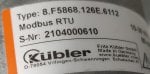
Modbus device: Slave- Absolute multi turn encoder by kubler Modbus RTU
Master- PC(Windows 10)
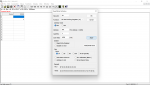
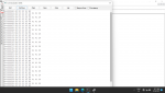
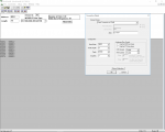
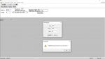
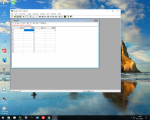
Hi everyone. I have been trying to change slave id of the encoder using Modbus poll software and an RS485 converter while testing out encoder with default node id 63
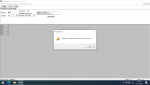
Insufficient bytes received
error pops out. I have read other posts over this forum about Modbus but it didn't helped me. I have attached required files about the problem. Hope someone help to figure this out.
Master- PC(Windows 10)
Hi everyone. I have been trying to change slave id of the encoder using Modbus poll software and an RS485 converter while testing out encoder with default node id 63
Insufficient bytes received
error pops out. I have read other posts over this forum about Modbus but it didn't helped me. I have attached required files about the problem. Hope someone help to figure this out.
Attachments
-
627.8 KB Views: 51
-
1.3 MB Views: 54
-
 849.4 KB Views: 96