Facebook
 Google
 GitHub
 Linkedin
Controlling and Troubleshooting Common DC Motors
Direct current (DC) motors have existed since the late 19th century. What sets these motors apart from AC models, how do you control them, and how can you tell when it’s time to repair or replace them?
What is a DC Motor?
DC motors are a classification of motors that, as the name suggests, are supplied with a constant voltage. Unlike AC motors, which rely on the natural fluctuation of the current in the windings to create a rotating magnetic field, DC motors must use some form of external control to alternate the magnetism and drive with continuous motion.
How Does a DC Motor Work?
There are two main categories of DC motors: those that have carbon brushes (called 'brushed DC motors,' or simply 'DC motors') and those that do not (which are called 'brushless DC', or 'BLDC motors').
How Does a Brushed DC Motor Work?
The brushed DC motors are the most simple, requiring no external control circuits. As such, they have existed for many decades. A constant, single-polarity (DC) voltage is supplied to the leads. One or two pairs of spring-loaded carbon brushes cause the electricity to flow to the rotating rotor windings. When the motor turns one-half or one-quarter of a revolution, the electricity is flipped (or ‘commutated’) so that the magnetic field is reversed.

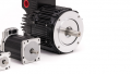
Figure 1. A set of brushed DC motors.
How Does a Brushless DC Motor Work?
Although there does exist a category of motors specifically called ‘brushless’ DC, or BLDC motors, this method actually describes any kind of motor that uses external control circuitry to alternate the polarity of the magnetic fields at the right time. The advantage is less friction and higher efficiency, as well as the ability to control the entire operation from the outside of the rotor, making this more like an AC motor.
These motors include the standard BLDC motors, but also a category called stepper motors, which make use of more poles and windings, allowing an external driver board to control the magnitude and polarity of each winding, which 'steps' the motor forward and reverse in tiny increments. These are incredibly useful for CNC machines with fixed travel distances.
How Do You Control the Speed of a DC Motor?
Speed control depends on the variety. For a brushed DC motor, the amount of current will determine the strength of the magnetic field generated. To increase current, we have two options, one more favorable than the other.
The less ideal approach is to decrease the supply voltage to reduce the magnetizing current. This is less ideal just because as the voltage decreases, so will the current, and the driving power of the motor is reduced exponentially. True, the motor will drive slower, but with less power, and the load might just grind the whole system to a stop prematurely. Instead of moving slower, all movement is halted.
Pulse Width Modulation (PWM) Speed Control
The superior approach is by means of a common control algorithm known as pulse-width modulation, or PWM. This method turns the supply voltage on and off rapidly to generate quick spikes of current at full power. The average time spent at full power will equal the equivalent speed of the motor as a % of full speed, but while energy is applied, the driving force is still at a maximum. This is superior to simply lowering the voltage to achieve lower speeds, since lowering voltage also reduces torque. PWM is by far the most common method of driving brushed DC motors.
Electronic Speed Control (ESC) Board
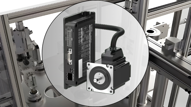
For the brushless variety, external circuits must compute the appropriate time to reverse the magnetizing voltage. For this reason, stepper motor driver boards and brushless electronic speed controllers (ESCs) are equipped with microcontrollers. They depend on a signal from another controller to convert a pulse series of step inputs (in the case of a stepper) or the PWM signal (in the case of BLDC) into the appropriate voltage polarity alternation. As the cost and size of ICs decrease, these driver circuits are very easy to obtain.

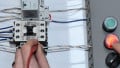
Figure 2. A variety of stepper motor driver boards.
How Do You Reverse a DC Motor?
Reversing a DC motor is also dependent on the type of motor being used.
Reversing a Stepper Motor
The simplest DC motor to reverse is the stepper motor, although this is due to the rather complex design of the driver IC. The board is driven by a step and a direction input. If the direction input is a logic high, the motor spins one way, while a logic low sets rotation in the other direction. When the direction is determined, a pulse to the ‘step’ input will rotate the motor a fraction of a rotation and hold until the next pulse.
Reversing a DC or BLDC Motor
Even though the supply device for a brushless motor is more complex than for a simple carbon brush DC motor commutation, the method of reversal is the same. The two motor wires are labeled as + and - for positive and negative supply. If those wires are swapped, the motor will reverse direction.
Common methods for reversing the wire polarity are to attach the wires to a DPDT switch or relay with the NO and NC wires cross-connected, or by using a circuit called an H-bridge which uses solid-state transistors in pairs to energize the path + to -, or from - to +, depending on which transistors are energized.
Brushless motor speed controllers may sometimes be found with reversing capabilities, where a moderate 50% PWM signal indicates ‘stop’ so that 0% and 100% may be fully forward and fully reverse, respectively. However, since many BLDC motors are used for propellors in UAV and underwater applications, there are a good many speed controllers with no reversing ability at all, and this must be done by manually reversing the motor wire polarity.
How Do You Test a DC Motor?
There are three areas of failure that might cause a motor to refuse to run properly: mechanical problems, internal circuitry, or external driving circuits.

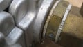
Figure 3. Sealed bearing attached to a DC motor drive shaft, this one showing a bit of rust, indicating too much humidity in the environment.
Mechanical Failures
Motors are rated to drive loads below a specified maximum, but the loads must be high enough to keep the speed in check and prevent overheating from excess RPM. Usually, a motor can run unloaded for short durations with no problem, but a load too heavy or light can cause premature failure. The bearings inside the motor allow the shaft and rotor to spin evenly and with low friction. Moisture, heat, loss of grease, and any bending of the shaft will certainly lead to the failure of the motor, with no option but to replace part or all of the motor.
With the motor disconnected, spin the shaft. It should rotate freely, with no sounds or grinding feeling (indicative of rust or wear), and it should keep rotating smoothly for a short time after you let go.
Internal Electrical (Winding) Faults
If the windings around the outside or inside of the rotor (the stator and rotor windings, respectively) have broken or shorted together, the resistance will change, and so will the current and, therefore, the magnetic strength.
Use an ohmmeter and measure between the + and - leads. The resistance should be somewhat lower than the data plate winding resistance (voltage divided by the full-load amps), since some impedance is introduced by the alternation of the electricity in the windings from the carbon brushes during rotation. If the resistance meter displays 'OL', the winding is open. If the resistance is abnormally low (which can be difficult to judge unless you have a new-in-box equivalent model motor nearby), some windings are likely shorted.
External Electrical (Driver Board) Faults
For each type of motor, the supply voltage should be sufficient to rotate the motor. The most basic test method for the brushed and brushless DC is to measure the supply leads with a voltmeter. Don't try and test the supply circuit’s resistance, those results will not provide any meaningful data. When the motor is running, the voltage should vary between 0 volts and the supply voltage, roughly linear, equivalent in percentage to the motor’s rated RPM.
Since the supply method is PWM, some digital multimeters update quickly enough that the voltage will seem to be jumping all over, and it’s hard to read. For these times, you might turn to an analog voltmeter whose mechanical dial will respond similarly to the motor itself, showing you a better average PWM supply voltage.
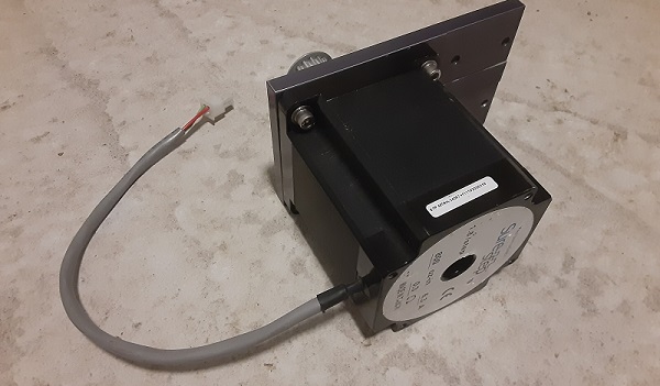
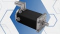
Figure 4. A large 4-wire stepper motor.
To test a stepper driver output, it can be useful to attach a few meters, just in case you have multiple lying around. Steppers have between 4-8 wires, and individual sets will be polarized as a step occurs. As the motor is slowly driven, you should see sets of wires progressively being energized, then dropping to zero volts.
PS: do not try and hand-spin a DC motor while it’s connected to the driver circuit. It can act as a generator and harm (even destroy) the driver circuit, a very costly error.
DC Motors
Although they are simple devices, there are many kinds of DC motors, each with benefits and some downsides that add to the design challenge for every unique situation.
All article images provided courtesy of the author, and featured image used courtesy of Adobe Stock