Facebook
 Google
 GitHub
 Linkedin
OpenPLC Programming: Manipulating Counters With a MOVE Command
Using a MOVE function block, a counter preset value can be loaded into an OpenPLC counter using a digital input. The technique allows flexibility in creating counter-based automation applications.
The traditional approach to programming any PLC counter’s preset count value is to hard-code an integer directly into the function block. The counter will then respond by incrementing the count value register and checking against the preset value during the execution of the automation application.
If the application requires a new counter preset value, the hard-coding process is repeated as described. But what if a new preset value can be implemented simply by pressing a button or using some other digital input?
In this project, we will use the OpenPLC software and a pushbutton switch to explore a simple ladder diagram method to change the preset count value while we learn the role of data manipulation functions for programming.
If you need a primer on using OpenPLC, please check out our introductory article!
Traditional Approach: Fixed Integers
The typical approach, changing the integer value directly within the counter, leads to potential inflexibility of the system. If we change batches or assembly processes, we must alter and re-download the code. Figure 1 represents this normal approach with the counter FB, the PV symbol, and the associated integer, which is ‘5’ in the case of Figure 1’s example.

Figure 1. Counter FB with a preset count value of ‘5’.
Using the Data Manipulation category of functions that exist in most PLCs, we can breathe new life into this preset value, allowing it to be changed easily using a MOVE command.
Data Manipulation
The PLC and a PC have a common element: the movement of data. Data, whether in binary, hexadecimal, or string format, is constantly moved from one register to another. This data movement or manipulation allows information to travel freely within a PLC’s computer architecture.
Figure 2 illustrates the concept of data movement within a PLC’s computer architecture, where some external trigger causes the data to shift from one register to another.

Figure 2. Data movement initiated by an external trigger.
The MOVE FB
In OpenPLC the MOVE function block can easily move data values from one register to another by applying an external trigger to initiate the action. The data movement action will allow an initial preset count value assigned to one variable name to be moved to another one with a single press of an external pushbutton switch. The new variable name wired to the counter FB preset count value pin will establish the total counting budget for the automation application.
In our OpenPLC example, an external pushbutton wired to an Arduino Uno digital pin will trigger the data movement action. To change the initial count value to the new counting number, the edit can be made in the tag listing instead of the PLC ladder diagram.
The MOVE FB is located in the ‘Arithmetic’ category section of the OpenPLC library. Figure 3 shows the location of the MOVE FB.

Figure 3. Location of the MOVE FB.
Initially, the MOVE FB Enable (EN) and Enable Out (ENO) pins are not visible. To allow access to these pins, click the ‘Execution Control’ check box (just above the preview in Fig 3 above).
The EN pin is critical because it allows the external trigger (a push button switch, in our case) to trigger the movement of variable name 1, wired to the IN pin, into another variable name 2, attached to the OUT pin.
Figure 4 illustrates the LD wiring of the MOVE FB with variable name symbols and an external push button contact.
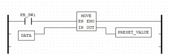
Figure 4. A MOVE FB Ladder Diagram example.
The DATA variable will be an int tag created in the Tag Listing and we will provide the tag with an initial value of 5. Likewise, the PRESET_VALUE is an int tag that will be attached to the counter PV in a later step. The data movement action will occur when the PB_SW1 is FORCE TRUE during a simulation session, or a real-world action after the project is finished.
Figure 5 illustrates the results of the MOVE FB simulation after execution.

Figure 5. A MOVE FB simulation.
Loading a Preset Count Value into a Counter with a MOVE FB
The implementation of loading a preset count value into a counter with a MOVE FB is quite easy to do. The LD application requires taking the logic built in Figure 4 and integrating it with an UP counter, or CTU. The complete application LD with the MOVE FB is shown in Figure 6.

Figure 6. An Up Counter Application with a MOVE FB.
The Tag Listing with documentation is provided in Figure 7. The complete application LD file can be found here.
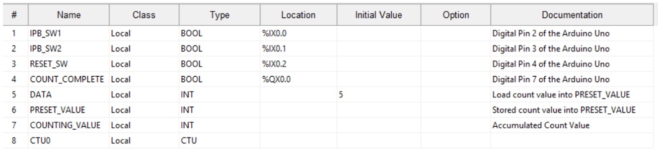
Figure 7. An Up Counter Application Tag List.
Explaining the flow of logic, pressing the IPB_Switch1 (our red industrial push button) will trigger the MOVE FB and transfer the count value of 5 into the PRESET_VALUE variable.
The counter itself is incremented with a press of IPB_Switch2 (the green industrial push button).
When the COUNTING_VALUE variable equals the PRESET_VALUE variable, the COUNT_COMPLETE coil turns ON. The COUNT_COMPLETE tag is attached to QX0.0, where a red LED is wired to digital pin 7 of the Arduino Uno.
Pressing the RESET_SW switch will reset the counter to 0 and turn OFF the LED.
As a reference, the completed assembly of the Data Manipulator - Counter project is shown in Figure 8.
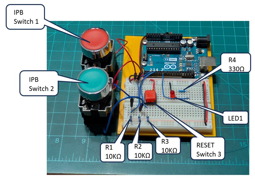
Figure 8. An Up Counter-Data Manipulator Demonstrator.
The electrical input/output wiring diagram is also provided below in Figure 9. Finally, a video clip providing an explanation and demonstration of the counter application may be viewed here.
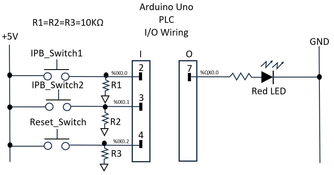
Figure 9. Arduino Uno PLC I/O Wiring Diagram.
Further Investigation
As a programming exercise, try to modify the LD where a DIP switch package can provide 4 individual preset count values. The selection of a DIP switch will load an individual count value into the counter, thereby providing a semi-automated programming feature for the demonstrator. This programming technique can be used with other variable-dependent OpenPLC FBs.