 Facebook
 Google
 GitHub
 Linkedin
Troubleshooting Linear Hydraulic Motion
Motion systems come in many forms. Hydraulic motion brings some unique problems, not seen in electric systems. This article will focus on how to recognize prominent failures quickly and correctly.
In industrial facilities across the world, hydraulic motion is used for a variety of different linear motion functions. Hydraulic motion is different from electric motion primarily because incompressible fluid powers it, rather than electrical protocol signals. Hydraulics can produce both rotary motion (spinning) and linear motion (straight-line movement), just like electric actuators. Also, rotary hydraulic motion often relies on encoder feedback, further increasing the similarity with electric servos.
Hydraulics vs Servos
Two main differences will drive the focus of this article. Hydraulic systems use valves to control cylinders instead of using waveforms to spin motors, as in electrical actuators. These valves are called servo valves and are operated by an analog voltage coming from a motion controller. Please note that these are not proportional valves. Proportional valves generally lack the fine control needed for closed-loop control systems. Another major difference is that linear hydraulic motion uses feedback sensors - the linear position transducer.
The following article will cover common faults related to these valves and transducers. We will cover the meaning of the error as well as some reasons you might have a system report this error.
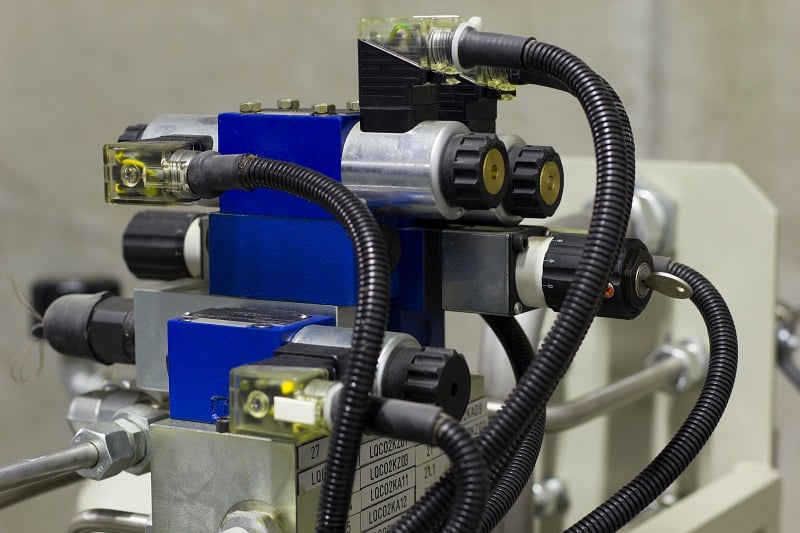
Figure 1. Hydraulic valves. Image used courtesy of Adobe Stock
Overtravel Error
Let’s start with an easy one. Just like with any other form of motion, if the motion axis is sitting at 23.132”, yet the limit is 22.000”, the system will report an overtravel fault. The only way to get around this is to bring the system out of closed loop and move it in open loop, or shut the system down and move it by hand.
In virtually all systems, positive and negative overtravel errors exist individually and will not display as a single overtravel error. The reason for this is that the negative and positive overtravel limits must be different from each other and held in separate registers of the controller.
Following Error
The following error occurs when the position of the system is too far away from the position the controller expects it to be at. If a system is told to travel from 0” to 5”, the controller will generate a path that the motion system should follow under its current tuning conditions. Halfway through the movement, you might expect to see a value of 2.5”.
Now what if it’s not at 2.5”? What if it’s only at 2”? In this case, with the system not following the path on which the controller expects it to take, we might expect a following error. There are several reasons this can happen.
First, the system may have lost pressure. Rule #1: Are the hydraulics turned on? It sounds foolish to even ask, but any seasoned professional will nod knowingly. Always make sure it’s turned on. Other options could be a manual blocking valve that has failed and is blocking the fluid in the system when it should not be.
Second, there might be a broken piece of hardware on the motion axis equipment. Check for broken or binding pieces of linkage. In my line of work, sawmilling, we sometimes drop massive logs onto motion-driven carriages. If we were to have a 5000 lb log with clamps holding 3000 lbs of force down on it, this may be enough to halt the motion axes if they need to skew the log aggressively for a cut. The broken piece of hardware may also be the cylinder itself! Or a blocking valve, as mentioned before.
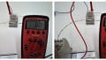
The third problem (and generally the most expensive) is a bad valve. Valves often cost upwards of $15,000. The best way to test a valve is to unload anything off the axis so it is free to move, then use open-loop voltage to force the valve to move. If open-loop mode doesn’t work, remember to check the voltage at the valve and make sure the meter reports both the feed voltage AND the control voltage. A Jog-Box is an alternative that provides hand-operated control so that all the wiring can be bypassed.
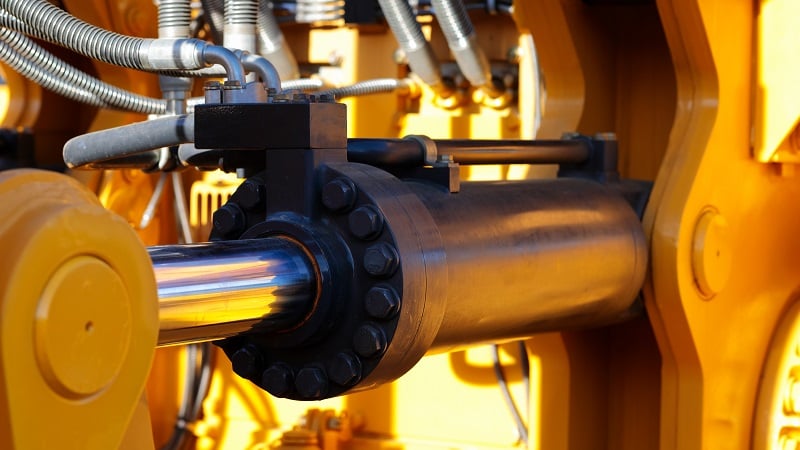
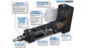
Figure 2. Hydraulic cylinders. Image used courtesy of Adobe Stock
No Transducer Error
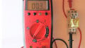
After that previous crazy error condition, how about an easy error? The No Transducer error appears when there is no input data detected from the transducer. This can be due to a failed transducer or a wiring failure. Standard electrical troubleshooting comes in handy here. Confidently working with a multimeter should lead the technician to the problem quickly.
Transducer Overflow Error
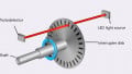
Linear transducers work by sending a pulse down the length of their rod. This pulse is reflected off a magnet in the cylinder and travels back to the sensor. The sensor receives the reflection signal and measures how long the pulse takes to return. The amount of time it takes to return is scaled by the sensor to determine the position of the magnet on the cylinder. They have a maximum and minimum travel time that they are programmed for. If a pulse returns in a longer time than the length of the sensor allows, the system will report an overflow error. There are generally two causes of this.
1: Transducer failure could be the issue. This is probably the easiest option when it comes to replacement.
2: If the cylinder sensing magnet fails, it could allow the waveform to continue without being reflected. If this happens, it may require a replacement of the magnet or the cylinder. This depends on how the cylinder was designed.
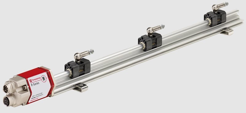
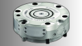
Figure 3. Magnetostrictive linear position sensor. Image used courtesy of Temposonics
Output Saturation/Output Overdrive Error
The Overdrive Error happens when the drive going out to the valve is at the maximum. This error is usually able to be changed so that the system continues to run in the overdrive state, but most systems will shut down if this fault occurs unless the program specifically tells it otherwise. This is generally a warning sign that a following error is close behind! If a system begins showing this error, conduct a hardware examination at the next possible opportunity.
Common Hydraulic Failures
This article is not meant to provide a comprehensive coverage of every failure type; it simply attempts to pinpoint symptoms and provide helpful advice on locating certain problems. As with all motion systems, the problems can be mechanical or control-related, and it helps to bring all related parties together to solve the root of the problem, not simply adjust and compensate to correct a deeper problem.


The first sentence in your article is inaccurate:
“Two main differences will drive the focus of this article. In both rotary and linear motion, hydraulics uses valves instead of waveforms to spin motors.”
For linear motion almost all hydraulic systems use hydraulic cylinders. These have no motor in them. The system has a motor that provides hydraulic pressure/flow, but the actuators themselves do not have an internal motor unlike electric actuators.