Tutorial: Arduino and AutomationDirect Merged in the ProOpen PLC
Having separately covered Arduino’s microcontroller platforms and AutomationDirect Productivity PLCs, it’s time to take the wheel of the ProOpen, a PLC that combines modularity with C++ programming.
Why is there so much interest in PLC programming? It could be said that because PLCs are the backbone of most industrial automation systems, of course it’s important to understand the intricacies of using such devices. This leads to an important question: why have PLCs become such an all-important control architecture in the first place?
There are many debatable opinions on this matter, but one of the ones I hold most firmly is the ladder logic programming structure; the ability to program within an environment that looks and feels like the electrical schematics that run the plant. Electricians, engineers, and technicians alike can understand and troubleshoot these programs without much difficulty.
Today, we’re going to expand that ladder logic horizon just a bit. AutomationDirect, known for a vast array of automation devices, including PLCs, offers a model called the ProOpen, a modular PLC with the brain of an Arduino MKR Zero microcontroller.
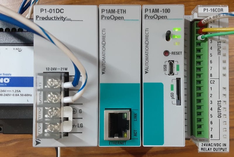
Figure 1. My bench setup includes a power supply, Ethernet adapter, CPU, and I/O module. You can complete this project with just the CPU and I/O module!
How is an Arduino Different From a PLC?
This is a great fundamental question. An Arduino is simply a board that provides easy access to a processor chip’s I/O pins. But beyond that, the programming environment is free, simple, and text-based, and the user community is vast and global.
If we want to get specific, there are two main distinguishing differences. The Arduino is programmed with a variation of C++ (text-based, NOT ladder logic), and the Arduino also does not have simple snap-on I/O modules, save for certain ‘shields’ that can be placed on stackable headers, but these don’t look much like PLC I/O modules that any control engineer would recognize.
Nevertheless, the ProOpen combines the power and flexibility of the Arduino MKR board and packages it into the DIN-rail mounted CPU, power supply, and I/O module series compatible with the Productivity 100 PLC series. If we can harness this, we have a pretty powerful PLC indeed.
Getting Started: What Do I Need?
This project, while not as costly as some PLCs on the market, still requires a couple of items to succeed. We will be using the P1AM-100 CPU and a combination input/output module, the P1-16CDR. In my setup, I also have included an Ethernet module and a power supply, but this introductory project will succeed without these.
In addition to the PLC itself, we also need a 24 volt power supply and micro USB cable that includes both power and data (your computer should register a new device in the device manager).
Since the programming uses the Arduino software, you can program this PLC on Windows, Mac, or Linux! This tutorial was tested on software version 1.8.19 (scroll down and find the ‘Legacy IDE’ button on the download page). I personally have not tested it on the newest version 2.0 platform from Arduino.
The hardware setup is very simple. The I/O module is attached on the right side of the CPU and fixed to the DIN rail. The power supply is connected, and I powered up the 24 volt supply before connecting the USB cable to the CPU.
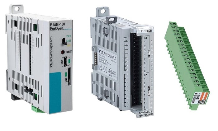
Figure 2. Required hardware: the P1AM-100 CPU and the P1-16CDR I/O module, along with a terminal block for wiring.
Configuring the Software
To properly use the Arduino software, you will need to add two elements:
- The library provides convenient access to all of the commands to run the I/O and communication abilities.
- The board manager provides information about the P1AM hardware itself.
These instructions are already excellently provided step-by-step in the manual from AutomationDirect, beginning on Page 1-5 and continuing until the bottom of Page 1-6.
For this tutorial, I am only using the Arduino IDE, not the add-on ProdictivityBlocks software. When you load the code, you may experience errors unfamiliar even to those who have used Arduino products, so be sure to check out the troubleshooting section later in this article.
Designing Your Code
If you are unfamiliar with the basis of C++ programming, it contains all of the same elements of ladder logic, but in a completely different format.
I have provided a template that helped me get started with any code I want to write, assuming I’m using the same hardware setup. Here is the code, beginning with the inclusion of the library at the very beginning. I will break it down and explain each component and how it relates to a ladder logic project.
Tag Name Variables
In this IDE, variable names are used throughout the code, perhaps many times, just like tags. Deleting and re-typing new tag names in every single instance would be a nightmare, so at the very top of the code, I created a section to define my input and output variable names.
In my first simple project, I have a blue button attached to input terminal 1, and a green button on input terminal 2. I also have the standard red LED indicator on the output module. You can follow my example and type in whatever tag names you wish to use.
The lines with ‘int’ refer to the integer values for each I/O point. These must be globally defined at the top of the code, much like controller-scope tags for all I/O addresses in a PLC program.
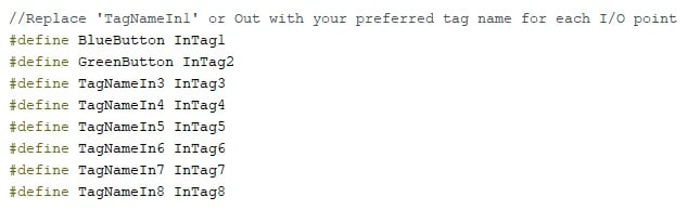
Figure 3. Defining the tag name variables. The first two are already set for my program. We’ll also need 8x for the outputs.
Routine: setup
All PLCs contain a first-cycle scan logic. Often we ignore this routine and leave it blank, but the setup routine in C++ includes the initialization of communication channels and the verification that the PLC is responding.
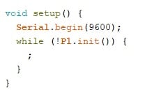
Figure 4. The setup routine initializes the serial communication (if we end up needing it) and verifies the CPU status.
Subroutine: readModules
In a typical PLC scan, the status of all input points are detected before executing any logic. This simple subroutine will obtain all input addresses on this combo module (it has 8 inputs and 8 outputs).
If other modules (even analog inputs) are added to the project, they can also be added to the readModules routine.
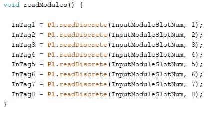
Figure 5. This subroutine reads all of the input module points. For convenience, we define the slot number at the very top of the program.
Main Routine: loop
The main routine performs three basic tasks in this order:
- Runs the readModules subroutine
- Checks all logic instructions in our code
- Runs the writeModules subroutine.
In step 2 is where our only code editing needs to take place, between the indicated // comment marks.
Rather than re-hash this If/Else statement logic, have a look at our previous article, describing how to recreate ladder logic in a C++ coding environment.
For my simple test, the code examines both the red and green buttons, if both are energized, the output LED will also energize.
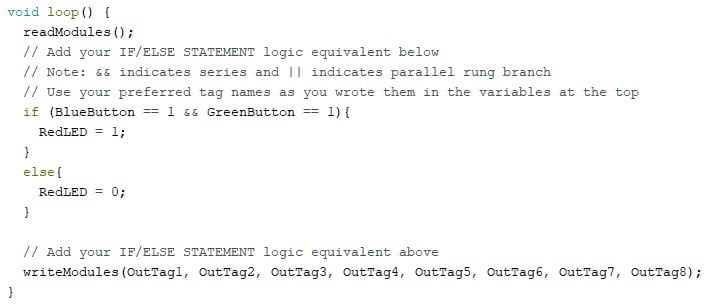
Figure 6. The main routine actually executes the user-defined logic. It doesn’t need to be ladder format, but that can help.
Subroutine: writeModules
Once the logic has been executed, the temporary status of all I/O points is stored, but not yet written to the I/O modules. The purpose of this final subroutine is to write those values.
This means that there will be a slight delay as the code increases in length, more similar to a traditional PLC and a bit unlike a typical microcontroller code, where the values can be written at any time.
The flexibility of the C++ environment allows the programmer to have far more control over when, how, and why the outputs respond to logic conditions.
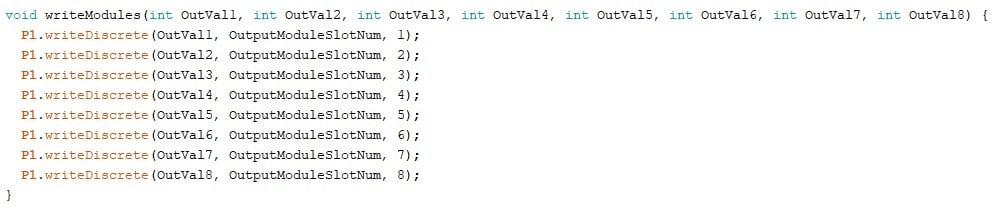
Figure 7. This routine takes in all of the updated tag values and writes them to the proper output terminals.
ProOpen Troubleshooting Tips
There are a few tips that can aid in programming that are a bit unique due to the presence of the MKRZero board inside.
First, always press the ‘verify’ checkmark button before uploading with the arrow button. This way, you can isolate errors to the either code errors or loading errors. Sort out the code errors first.
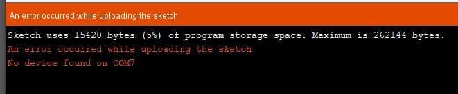
Figure 8. A possible COM error when loading a code.
Restart the Arduino IDE
Some errors exist because the COM port is currently in use from an existing project. Closing and opening the IDE can clear some problems and refresh board and port identifications. If this doesn’t work, move on to the next step.
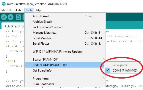
Figure 9. This shows the proper selection of the board and port for a Windows machine.
COM Port Number
If the program reports an error during the loading process, verify that the board is selected properly, and that the COM port is also correct. The following image shows the correct values (although your COM port number may be different).
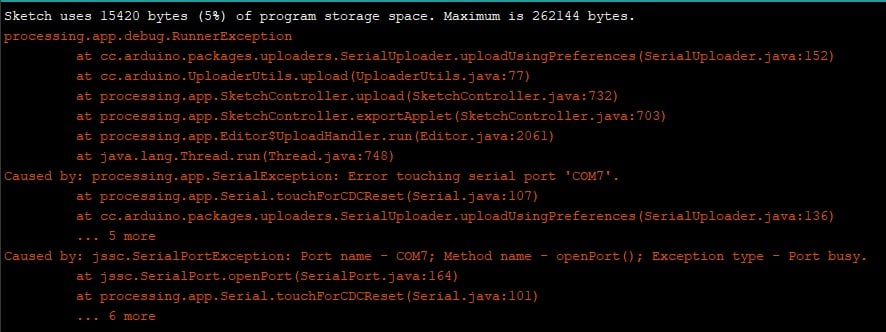
Figure 10. If this error is encountered, double-tap the Reset button, select the COM port, and upload again.
Reset Button for Bootloader Mode
When loading a program, there can be errors in communication. Compared to the familiar Arduino Uno board, there are differences in the chips that handle the translation between the USB and serial communications for the CPU. Simply pressing ‘Upload’ again or restarting may not solve the problem.
A common fix is to press the ‘Reset’ button on the CPU 2x times quickly, then select the proper COM port (it might change), and upload one more time.
This reset button puts the CPU into a mode that stops code execution and allows loading, sort of like putting a PLC in STOP mode.
Code Stops Executing
In some rare cases, the code seems to stop executing after a period of time (my experience was about 12 hours). In my case, the CPU was tethered to the computer via USB for that duration. After unplugging the USB and pressing ‘Reset’ 1x time, the code still failed to execute and required re-uploading of the code.
In a second test, the USB was disconnected immediately after successful upload, and the code continued to execute indefinitely (at minimum until the writing of this section, several days).
Using a Microcontroller as a PLC
This process of embedding a microprocessor into a PLC chassis isn’t really that far off from the reality of most PLCs. However, many would argue that this purpose limits the potential of the microcontroller, and while that might be true, PLC software certainly provides some extreme advantages in the industrial world, catering to operators and technicians unfamiliar with text-based coding. This kind of PLC is a nice compromise with some distinct flexibility advantages.
Have you used this PLC for some fun projects?
All images used courtesy of the author
We have plenty of other PLC and microcontroller tutorials, get some inspiration from a few more!
- Intro to Siemens S7-1200 PLC and TIA Portal Programming
- Intro to PLC Programming with Rockwell’s Studio 5000 and CompactLogix
- How To: Simple Programming with AutomationDirect Productivity PLCs
- Ladder Logic for the Arduino Opta PLC: Creating Your First Program
- Turn a Raspberry Pi Into a PLC Using OpenPLC