 Facebook
 Google
 GitHub
 Linkedin
Ladder Logic for the Arduino Opta PLC: Creating Your First Program
Arduino’s Opta mini PLC platform is supported by the new PLC IDE. Learn to create and download your first program and take advantage of built-in I/O for an easy introduction to the platform.
Arduino, the company known and loved around the world for introducing students and professionals to the world of electrical engineering, has made a push in the past year to capture a foothold in the industrial marketplace.
Industrial automation can be a challenging field to enter because of strict reliability and security requirements, brand familiarity, and compatibility with existing systems–some of which have been in place for decades.

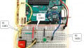
Figure 1. A simple test bench with the Arduino Opta—the ‘USER’ button at the top serves as the programmable input for this intro project.
What Arduino Board Supports PLC Programming?
Two new hardware platforms have been launched recently to meet various needs in the industrial environment. One of these, the Portenta Machine Control (PMC), was the first to be officially supported by the PLC development software for which you can find tutorials for basic discrete I/O control and more advanced analog and device connections.
The second platform, the Arduino Opta, has more recently been added to the list of hardware officially recognized in the PLC IDE. To get started with your very first PLC project on this platform, follow the following program and troubleshooting steps to set up success.
Create a New Arduino Opta Project
Some of the steps for initial project creation can also be found in our introductory article for the PMC platform.
Before getting started, it is recommended to download the most recent version of the IDE and the tools (both free and available from the official Arduino software site). Install both packages, which as of this writing, are version 1.0.3, which indeed supports the Opta platform.
After installation, open the software, and create a new project. Give it a name, which I will reference for my own project as Opta_Test_2 from this point forward, and be sure to select ‘Opta 1.0’ as the target.

Figure 2. Creating a new project for the Arduino PLC IDE.
At this point, you will need to download a first initialization sketch, but only on a complete reset or first use. The overview page should show the image of your Opta PLC, but scroll down until you find the ‘Other’ selection for manual sketch download. There should be a COM port selected (mine was COM 7 on first installation, the COM 5 was added after), then download.

Figure 3. First setup and initialization download of the PLC IDE code.
After the initial download, you can go online with the Opta PLC (On-line menu -> Connect).
The only other setup step is to activate the license. You may need to visit the Arduino online store and purchase a license key, which is relatively inexpensive (less than 20 USD).
Author’s note: I previously used the Portenta Machine Control platform on this laptop. When I pressed the button to activate the license for this Opta project, it did so immediately, and it accepted the license after a complete reboot (both the 24 V and USB were removed). I had purchased a license number but wasn’t prompted to enter it. If this is your first time using any Arduino PLC, you may be required to enter the license number. Will update as this information is clarified.

Figure 4. After activating the license, be sure the status says ‘OK’ to continue programming.
Building Your First PLC Ladder Diagram
Before actually plugging in contact and coil commands into a ladder rung, we must first create the right I/O tags, then make sure we have a proper ladder program space in which to build.
Mapping Physical I/O in the Opta PLC
The Opta provides us with a nice advantage for this ‘beginner intro’ type of program. There is a built-in button on the top of the device with the label of ‘User’. This button doesn’t perform a default function—it’s just a handy button that we can use for simple projects without the need for extra hardware.
For the output, we’ll just use a built-in relay output.
For experienced PLC users, there will be one warning, but it’s a feature, not a problem!
When you program an output to energize, the corresponding LED will NOT light up. They are not connected internally, as most output modules might be. The LEDs are programmable separately, including the ‘User’ button, so with a simple program, the relay will audibly ‘click’, but the lights won’t illuminate. Not until we program them, that is!
Navigate to the ‘Resources’ tab -> 'Button Inputs' (shown below) -> then assign the one called ‘User’ with the variable name 'User_Button' (shown in the second image below).

Figure 5. I/O Mapping.

Figure 6. Defining the USER button with a variable of the same name.
Repeat this process in the Relay Outputs tab, locate Output 1 (called O1), and name it simply ‘Output_1’.
Obviously, for a real-world project, you would use the name of the real-world output device, perhaps a solenoid or motor drive.
Create a New Ladder Diagram Program
The default ‘main’ program created is structured text (ST). This is a great platform to work with, but for automation engineers, ladder diagrams are often the go-to, so this article uses ladder logic.
To create this new Ladder Diagram interface, navigate to the ‘project’ tab (lower left corner). You should see a ‘main’ up near the top, and it will have a default counter program, all in structured text.
To create the new LD program, first click on the top-level tree project name, as you can see in the image below–mine is ‘Opta_Test_2’. If you don’t select the top-level project tree, the options for ‘New program’ will be grayed out.

Figure 7. Creating the new ladder diagram (LD) program.
Select a New program, and you can choose the type, name, and how it will run. ‘Fast’ means that it will be continuously running in a cyclic fashion.

Figure 8. Be sure to assign the task, or else the program will not actually execute once downloaded.
Troubleshooting tip: If you forget to assign the task at this point, the program will not run when downloaded. But don’t worry! You simply need to tell it when you want it to scan and activate the outputs. All PLCs are like this. If the program is not running, no outputs will energize. In the Project menu, just open the 'Tasks' list, right-click on the 'Fast' task, and add the program from here.

Figure 9. Adding a program to the 'Fast' task.
Program the Ladder Logic
Finally, we can create the ladder program! Double-click on your new program, and there will be a blank input contact and a blank output coil. I had to scroll to the right to see the output coil, but it should be obvious if you have a large screen.
A double-click or right-click -> properties allows you to enter the variable names, just as shown below.

Figure 10. Our first Arduino Opta ladder logic program!
On-line -> Download code, and you should now have a running PLC program!
Why Don’t the LEDs Work on My Arduino Opta?
As mentioned before, the I/O LEDs are not hard-wired to the I/O pins like on a normal PLC.
The Resources tab also has a menu for LED Outputs. Head back over there, and let’s add a variable name to L1 and L8. L1 is the output LED, and L8 is the blue LED beside the ‘User’ button. You can see the variable names I chose below.

Figure 11. To energize the LEDs, first assign them the correct variable names.
Back in the ladder program, we must command these LEDs to energize any time the input is active and, therefore, when the relay output is also energized. Right-click on the output coil and select ‘coil’, which will add a new output in parallel with the first.

Figure 12. Adding the LEDs to the main ladder diagram structure.
Re-download, and now the relay output and the LEDs should be working as expected.
Debugging Variables
Congratulations on your first Arduino Opta program! You can finish here if you’d like, but there is one more useful feature to discuss.
You can add variables to a ‘watch table’ to view their status in real-time. This is handy if you think your program should be working but the PLC isn’t responding. Is the program in the code or the hardware?
Click on any command or variable in your ladder diagram, like ‘Output_1’. Navigate to the top ‘Debug’ menu and Add symbol to watch.

Figure 13. Adding variables (symbols) to a watch list can identify problems in the code and hardware.
Now, there will be a new window to the right of your ladder diagram. This will give you the current value of a BOOL, integer, or float so you can more easily view the status (you Arduino folks: this is like the ‘Serial Monitor’ and you know how useful that can be).

Figure 14. The watch table when the button is unpressed (left) and then pressed (right).
Arduino PLC Ladder Logic Programming
Arduino has come a long way since the initial launch of the Uno R3, and many of us have known and loved them since the beginning. Stay tuned to learn more about the constantly evolving PLC and edge capabilities that these products can add to industrial innovation!
If you have an Arduino Portenta Machine Control (PMC) and you still wish to learn PLC programming, check out our other tutorial articles for Arduino!
Arduino PLC IDE Tutorial 1: Basic Ladder Logic Programming
Arduino PLC IDE Tutorial 2: Analog I/O and External Devices
If you only have a spare Uno or other similar board, yet are still interested in learning new PLC functions, there are a few other options available to learn and explore.
PLC Ladder Logic on an Arduino: Introduction to OpenPLC
Recreating PLC Ladder Logic in an Arduino C/C++ IDE
Want to test your knowledge of PLCs? You think you N.O. a lot about ladder logic? Are you a normally-open or normally-closed minded engineer?
Check out our PLC Programming worksheet!


Do you connect a device in Modbus with RS485 o TCP only with PLC IDE ? A device like client and a device like master.
In the initial preloaded example the leds would flash, and off USB only, I cannot get the relay or leds to flash with this. But I see in the watch the variables changing what am I doing wrong