Facebook
 Google
 GitHub
 Linkedin
Tutorial: Single-Axis Motion Control with CMZ Drive, Part 2
In this article, we continue our tutorial by designing a simple structured text motion program and downloading it to the onboard PLC.
Following our previous article where we configured a single motion axis, we will now investigate the design and execution of a PLC program directly onboard an SBD servo drive from CMZ Sistemi Elettronici, thanks to a generous loan of equipment from Bright IA, a system integrator from Texas.
For many motion projects (especially complex ones), we rely on a PLC or IPC to calculate and deliver the set points to the drive. But with this controller, including a small number of configurable I/O points, we can design a simple motion program without even using a PLC.
Programming a Cycle
To start the embedded PLC programming script, go back to the Main screen and navigate to the Program tab. This will enable you to create and save a new program. After it’s complete, it must then be compiled and downloaded to the PLC.
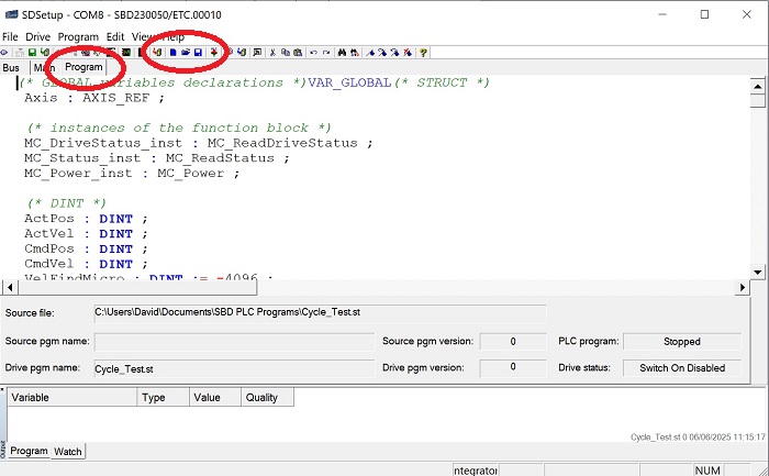
Figure 1. Navigate to the Program tab, then create a new program.
Create a new program, and we will be using the example provided in the CMZ documentation for the management of a single axis, although there will be some noted modifications for our application.
For this discussion, I will break up the various sections of the code as color-formatted images, but you can retrieve the entire code in text at the end.
Declaring Variables
The first step is to define all of the data points, including velocities, target positions, and more. The code from CMZ (including the comments) shows the default values, but the red circles indicate locations where we must insert the values for our own system.
Examine the image below.
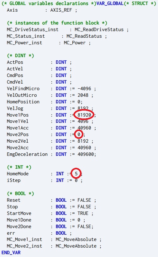
Figure 2. Setting up global variables.
In the DINT category (double integers), VelFindMicro and VelOutMicro work together to define the homing speed on the first program execution cycle. The VelFindMicro velocity of -4096 means that the axis will travel (quite slowly) in the negative direction until it meets the homing switch. As soon as that happens, it will then travel back in the positive direction, even more slowly, until the switch is released. The moment that happens, the current position is set to 0, thus completing the homing cycle. I would not recommend adjusting these values unless you are comfortable with faster homing.
Next, we see three elements defining Move1 and Move2. The position (Pos) is critical because the length of your axis is likely different from any default value provided by the example code. In the previous article, we measured the distance traveled by one rev of the motor (depends on your belt/ball screw setup, mine is 8.5 mm), as well as the number of increments per revolution (default is 8000). Some simple math shows that this default code would cause my axis to travel:
\[81920~inc \cdot \frac{1~rev}{8000~inc} \cdot \frac{8.5~mm}{1~rev}]\
This equals 87.04 mm, or roughly 3.5 in.
You can increase the velocities as you feel comfortable, but verifying the target position is far more important in this intro tutorial than teaching how to make the motor run faster.
Moving to the INT (integer) category, there is a selection for HomeMode, which deserves some explaining.
Homing Methods
There are 12 different methods of ‘homing’ the axis in the SBD. Many are related with slight variations, so I will explain each of them.
| INT Value | Description |
| 1 | Travels to the homing switch (defined by your I/O). If it hits a software or hardware limit switch, it will halt with an error. This is the value I used in my code, since I do not have limit switches. |
| 2 | Travels to the homing switch (defined by your I/O), then finds the encoder’s zero mark. If it hits a software or hardware limit switch, it will halt with an error. |
| 3 | Travels to the homing switch (defined by your I/O). If it hits a software or hardware limit switch, it will reverse direction until it finds the homing switch. |
| 4 | Travels to the homing switch (defined by your I/O), then finds the encoder’s zero mark. If it hits a software or hardware limit switch, it will reverse direction until it finds the homing switch. |
| 5 | Does not move, simply sets the current position to 0 (or whatever is in the HomePosition variable). WARNING: If you have properly homed the axis, but then it halts in a random position and the code is re-executed, this will become the new zero position, and your target positions will likely travel beyond your actual hardware limits. |
| 6 | Searches for the encoder’s zero mark in the direction defined by the velocity. |
| 7 | Travels to the limit switch (defined by your I/O) in the direction defined by the velocity. |
| 8 | Travels to the limit switch (defined by your I/O) in the direction defined by the velocity, then finds the encoder’s zero mark. |
| 101 | Same as 1, but any offset value (old position - new position after homing) is stored in memory and can be restored after power-cycling the drive. |
| 103 | Same as 3, but any offset value (old position - new position after homing) is stored in memory and can be restored after power-cycling the drive. |
| 105 | Same as 5, but any offset value (old position - new position after homing) is stored in memory and can be restored after power-cycling the drive. |
| 107 | Same as 7, but any offset value (old position - new position after homing) is stored in memory and can be restored after power-cycling the drive. |
Initializing the Drive
The Main program begins by defining the local variables, reading the status and position of the drive, and then handling errors and stops. These are pre-defined functions, so for our purpose, they do not need to be adjusted.
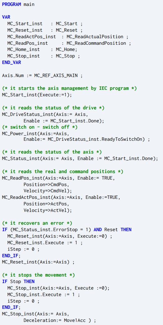
Figure 3. Initial setup functions in the Main program.
Calling the Motion Functions
The next and final part of the Main program is where the real fun happens.
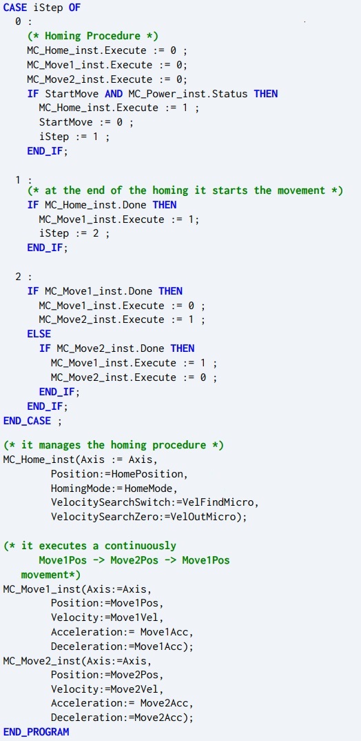
Figure 4. Motion in the Main program.
In the previous initialization, the variable iStep is set to = 0. If the drive is ready to move, this will execute the homing procedure and set iStep = 1. There it remains until the homing procedure is complete, when it executes the move to Position 1 and sets iStep = 2.
It remains with this value, toggling endlessly between Move2 when Move1 is complete, and then Move1 when Move2 is complete.
Exception Handling
The final program element is the exception handler. This part also does not need to be configured in the case of a simple bench test.
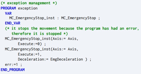
Figure 5. Exception management program.
The entire code can be found in the GitHub project: CMZ_SBD_Example.
Copy and paste the code into the Program section of SDSetup, and make sure to adjust those target positions as necessary. Click Save.
Compiling and Running PLC Code
The final step includes three parts. First, compile the code with the Compile button. Then, after this is completed, download it to the PLC (which again, is already on the SBD; we are not downloading to an external PLC).
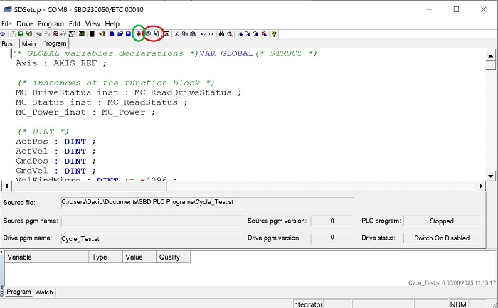
Figure 6. Compile and Download buttons (red) and Run button (green).
Finally, click the button to run the PLC, and the status should update.
If it is successful, the axis should start slowly moving to the home switch, click the button, then very slowly back off. Once it’s released, it will more quickly begin its motion cycle back and forth between targets.
At this time, you could increase the Move1Vel and Move2Vel in the global variable, if you feel comfortable.
Great job! You have downloaded a running motion program to a CMZ servo drive PLC.