Facebook
 Google
 GitHub
 Linkedin
Tutorial: Single-Axis Motion Control with CMZ Drive, Part 1
In this article, we’ll explore the SBD drive series from CMZ, including setting up the motor, scaling and testing the axis, before creating a simple motion program in the onboard PLC.
Motion is critical in automation. Virtually every system includes some moving element. Perhaps this is as simple as a pneumatic cylinder or a solenoid, but more often, there are motors involved. If the motion must run with a very precise speed or positional path, we are likely to find servo-driven motion axes.
Servos are just standard brushed or brushless motors with a built-in sensor for feedback. A drive unit receives this feedback and automatically calculates the next speed or position for the motor on a microsecond basis.
In this article, we will walk through the steps of setting up and testing a single-axis of motion on an SBD servo drive from CMZ Sistemi Elettronici, thanks to a generous loan of equipment from Bright IA, a system integrator from Texas.
Motion Project Hardware
There are two important segments of any motion control system, each with multiple components.
The Linear Axis
The linear axis includes the sliding components and the coupler to fix the ball screw (or belt sprocket) to the motor. This is built by the end user or by an engineering team, with all of the parts chosen according to the specs of the load to be moved.
In my benchtop setup, I have a ball screw drive with a pitch of .333 inches per rev (or ~8.5 mm/rev). The working length of the axis is 450 mm. I also have a single limit switch at the motor end of the axis to use for homing.
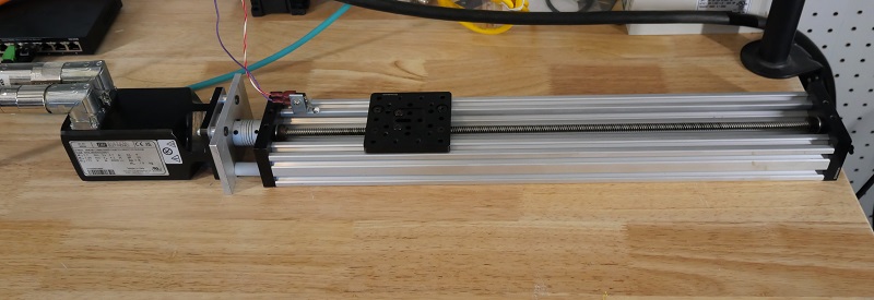
Figure 1. My linear axis. Yours might have a different length and thread pitch, as well as placement of the homing/limit switch(es).
Note these considerations to remember at this time for when testing the axis.
- How much of the total stroke does your mover/carriage consume? My carriage is just below 80 mm, so if I chose to drive my axis to a 450 mm target, the carriage would collide with the far end. Motion is fun, but don’t forget about geometry!
- There may be some conversions between the number of motor increments (steps) and the number of mm in a single revolution. I like to disconnect the motor from the axis and give the ball screw a single full rotation and carefully measure the length of one rev.
The Servo System
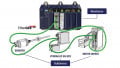
This CMZ servo control system comprises the drive unit, the motor (with encoder installed), and the two cables that provide power out to the motor and feedback into the drive.
The drive unit is powered with 1-phase 230 volts AC, and it includes a set of assignable I/O pins, one of which (input 0) receives the signal from the homing switch.
Two STO (safe torque off) inputs are connected directly to +24 V for this test setup. For your own setup, perform a risk assessment: are there any potential hazards that may require you to place an E-stop in series with these STO inputs?
The motor is an MMD 65 made by CMZ with an output torque of 1.7 N-m, more than sufficient for my small, unloaded axis. For mounting, it has a hole diameter of 63 mm.
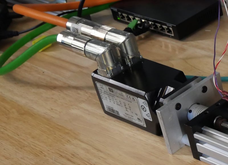
Figure 2. The motor with the power and encoder cables (left end) and the adapter plate and coupler that connect it to the linear axis (right side).
Commissioning Software
SDSetup is the environment in which all setup and programming of the drive takes place. We will begin with setup steps in this tutorial, but one of the advantages of this drive over many others is that a structured text PLC program can be written and executed directly on the drive. Simple PLC programs can be run without the need for an actual PLC.
By the time we have finished this series, we will have built and executed a code that will drive the axis back and forth between set points.
Verify Drive Operation
Before we run SDSetup, we should connect a micro USB to the SBD drive. This will be the simplest connection without having to run the EtherCAT connection through a PLC. When the SDSetup software starts, it will prompt us to make a connection with a COM port. Device Manager can help identify which COM port is active.
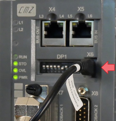
Figure 3. USB connection port, X6.
The Main screen displays information about the drive. Check the voltage of the input and the Bus, and ensure that they accurately reflect real values. If so, the drive is powered on and the software is communicating.
At this time, the STO light should be green, and if you have connected your homing switch to input 0, then it should illuminate green when the switch is pressed.
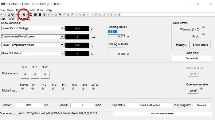
Figure 4. Green STO indicator, and Drive Setup button (red circle).
Set up the Axis
From the Main screen, we can select the Drive Setup button, which links the operation of the motor to the physical axis system.
The Setup screen has several useful tabs. First, ensure that the proper motor is selected; that is, the entry in the drop-down menu should match the motor dataplate’s part number.
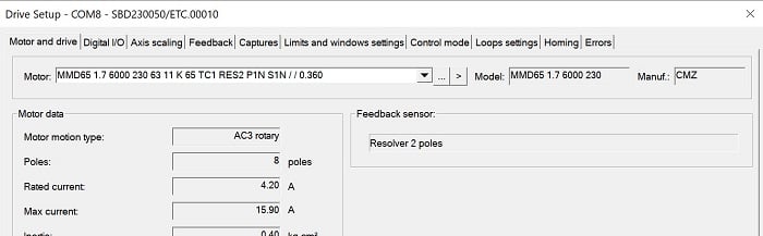
Figure 5. Select the proper motor.
Next, move to the Digital I/O tab. From here, we can set Input 0 to IN - Home Switch. You can select Active Low for an N.C. limit switch or leave it the default Active High for an N.O. switch.
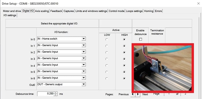
Figure 6. Digital I/O. My ‘In 0’ is set for the homing switch. The red square highlights the actual homing switch.
The next tab, Axis Scaling, is very important because without testing the motion, we can collide with the limits. Most of the defaults should be left as-is, but verify that the “Test the motor movement” box on the right side has a profile target position of 8000 inc/rev and press “Start.” The sliding axis should move away from the motor exactly the distance that you measured earlier with one revolution of the ball screw or belt sprocket.
- If the axis does not move, check the Drive information box for errors, and open the Error window at the bottom to diagnose.
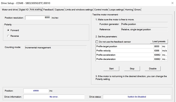
Figure 7. Axis scaling, with the test Start and Stop on the right side.
These test motions are relative, so you can type + or - values in the target position box, and test various velocities so that you have a grasp of how the velocity units relate to mm/sec.
The last tab is the Homing tab. There are many homing methods: software and hardware switches, directions, motions after switch trigger, etc. The manuals define these methods, so I will only explain the one I chose. The method (-27) means that it will travel at a preset speed in the negative direction until it hits the homing switch, then very slowly moves back in the positive direction until the switch turns off, then it sets the current position to 0.
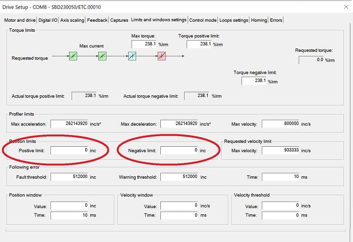
Figure 8. Input for positive and negative software limits.
You may also wish to adjust the “Limits and windows settings,” which can limit the travel distance if it exceeds certain increment limits. But be careful: If the homing method is incorrectly chosen, it will reset the current position to 0 at the wrong point, and the software limits will NOT prevent a collision.
Next Step: Programming
Now that we have set up the drive, the next step is to create and execute a motion program from the onboard PLC.