Using Sensors with Open Collector Outputs
This article discusses how to use sensors with open collector outputs and learning some of the module connections involved.
Most industrial sensors are meant to connect to PLC input modules with designations of either sourcing or sinking. The sensors are represented with terms to match NPN and PNP, respectively. However, in a few cases, some unusual terms appear.
One of the more confusing is the idea of ‘Open Collector Outputs,’ which are often found on encoder devices. A simple explanation can help to define how to use these kinds of sensors.
Using Sensors with Open Collector Outputs
Sensors are an essential part of every control system. Wiring strategies can vary slightly depending on the brands and types of sensors used. Fortunately, the variety of wiring styles is not too diverse.
This allows a technician to locate and connect an equivalent sensor, even if it didn’t happen to be the same part number called for in a datasheet.
There are a few common recognizable terms used in discrete (digital) sensors, notably PNP and NPN. These sensors are designed to match respectively with sinking and sourcing input terminals on the controller.
There is a less common term that appears particularly on encoder devices, but in a few other circumstances. Since it is less common, there is not quite as much attention devoted to defining what it is and how it works - and most importantly, how to connect the devices. This term is ‘Open Collector.’
Transistor Model
The name Collector comes from the model of the transistor, so it makes sense to begin a definition with a brief look at how the transistor is connected inside the sensor.
On the left side, the encoder circuitry (not shown, but consisting of LED emitter/detectors as needed and comparison amplifiers) uses the 24 volts and ground supplied by the power connector, and it outputs a small voltage to the signal circuitry through the Base pin of the transistor.
That signal circuitry on the right side is an NPN transistor that connects the PLC input to ground. The PLC input is directly connected to the Collector pin of the transistor. This provides the name Open Collector, since the wire is open at the end of a wire harness until connected to the PLC. The ground connection is the transistor’s Emitter pin.
When the sensor signal is high, the transistor allows current to from the PLC to ground. When the sensor signal is low, the transistor turns off, and current is no longer able to flow from the PLC.
In no case does current ever flow from the sensor to the PLC. This means that the sensor would be considered a Sinking sensor.
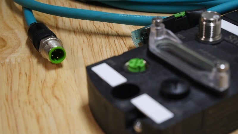
The connections to the outside world still consist of a +V, signal ground, and signal wire, as shown in the diagram. This is exactly like most other 3-wire sensors. In the case of encoders, most will have a wire harness consisting of more than one output. You will still connect the +V and signal ground, but have an additional number of signal wires.
In these cases of multiple signal wires, be sure that your input module can accommodate a sufficient number of encoders. For example, if an encoder has 3 signal wires connected, an 8-input module can only enable 2 encoders. If the encoder has five signal wires, that 8-input module could only operate with one encoder.
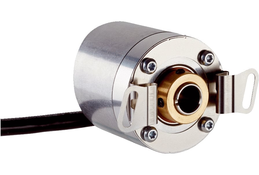
Open Collector Incremental Encoder. Image courtesy of SICK Sensors.
It is important to know that an NPN transistor is always used to construct Open Collector sensors, making them the same as all other Sinking-type sensors. That means you must use a Sourcing input module, which is a bit less common than Sinking modules.
The main reason for using NPN transistors in these applications is that the PLC can supply any voltage to that Collector as required, even though the sensor itself is connected to a 24 volt supply.
If the controller is a 12-volt system, the Collector will connect those 12 volts to ground. If it’s a 5-volt or another 24-volt system, it will still return to ground in every case. The alternative is a PNP transistor, which would be limited to supplying the source voltage only. So if you had a 12-volt control system, you would have to find a 12-volt power supply just for that sensor, which is not a very practical wiring system.
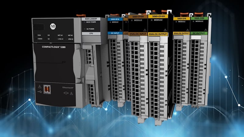
Module Connections
For encoders, special high-speed counter modules read the signals, since those encoder signals can change extremely quickly.
For specific details on this kind of module, consult the distributor for your preferred control system and ask about HSC (high-speed counter) and their capabilities. If you plan to use an Open Collector type of encoder, make sure the HSC inputs are sourcing.
For a standard 3-wire sensor with a listed ‘Open Collector’ output, the signal wire from the cable can connect directly to the PLC input terminal, but again, at the risk of being repetitive. It must be a sourcing input module.
A good lesson to learn from these unusual wiring circumstances is that it’s often useful to understand why something works to use it properly. Sometimes it’s tempting to look for the quick answer or wiring diagram, but that only solves a problem for the moment. By taking the extra effort to learn the theory of something more complicated, it might open up new opportunities to design better systems and solutions in the future.