Facebook
 Google
 GitHub
 Linkedin
What Do Light-on and Dark-on Mean for Photoelectric Sensors?
Industrial sensor applications face challenges of digital or analog, NPN or PNP, normally closed and normally open, but for optical sensors, the terms “light-on” and “dark-on” must also be understood.
Optical sensors are very common in industrial applications, but they don’t always use the same terminology as most other switches and sensors.
The discrete sensors include one notable difference, which will be discussed in this article. Most optical (or photoelectric) sensors do not include the industry-standard notation of “normally open” or “normally closed,” as we would find affixed to every limit switch, push button, selector switch, and most other discrete sensors.
Instead, we often encounter the terms “light-on” and “dark-on” for these optical situations, and there are four different ways in which this appears on a sensor spec chart:
- Light-on
- Dark-on
- Complimentary Light-on/Dark-on
- Selectable Light-on/Dark-on
Not every optical sensor manufacturer uses this notation, but it is common enough that it deserves an explanation.
Light-on
The term “light-on,” sometimes called “light operate,” simply means that the output signal will energize in the presence of a beam of light. As we know from other articles about photoelectric sensors, there are three types: through-beam, retro-reflective, and diffuse reflective. All three varieties are designed so that the presence of light must be strong enough to trip the detection circuit and output a signal.

Figure 1. All photoelectric sensors will specify if the output is active in the presence or the absence of light. Image used courtesy of Adobe Stock
When we select a light-on mode sensor, we can interpret this to mean that the output signal will be energized only when the beam of light from the emitter device or the retro/diffuse reflection exceeds the threshold mark.
This terminology does not override or negate the PNP/NPN output polarity. A PNP output signal may energize when light is present. Similarly, an NPN signal can also energize when light is present. Sensor specs will report both the polarity and the light/dark mode.
Dark-on
The inverse of the light-on mode is, naturally, “dark-on,” sometimes called “dark operate.” This means that the absence of light will trigger the output. It doesn’t mean that absolute darkness must be present–simply that the light value must fall below the threshold. This threshold may be fixed in the embedded sensor electronics, or it may be adjustable through teaching functions or a trimmer potentiometer.
Why do some manufacturers avoid using the familiar “normally open” and “normally closed” terms we see in other sensors?
When we look at the operation of the three types of sensors, we would have to mix and match terms between varieties.
For example, in a through-beam or retro-reflective sensor scenario, the normal state would be when the object is gone–when the light beam is unbroken. This is our normal scenario when the light beam is being received by the sensor.

Figure 2. In this through-beam sensor, the receiver is energized in the presence of light (no object detected). Image used courtesy of Adobe Stock
In contrast, for diffuse reflective sensors, the normal state still refers to the object being gone, but in this case, the object itself is the reflector. So when the object is gone, the sensor is not receiving light.
Using the above examples, would “normally open” mean that the sensor is energized when the object is present or when it’s gone? Most likely, we need to carefully explain the behavior in the datasheet of each sensor to avoid confusion.
Instead, we turn to the simpler method of simply identifying if light is present on the sensor or not. It’s much easier to predict the sensor’s behavior.
These sensors that are either light-on or dark-on have three standard wires: +V, -V, and the output signal. Sometimes, a fourth teach wire may be present.
Complimentary Light-on/Dark-on
Flexibility is the name of the game for modern industry. We might have reasons for choosing certain sensor output modes, like energizing in the presence or absence of an object. Not every application needs to be energized when the object is present.
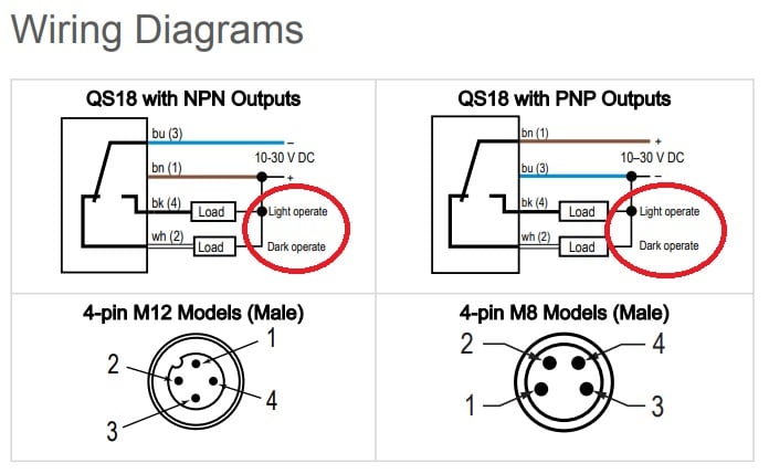
Figure 3. This diagram shows complementary light on and dark on (using the term “operate”) with both NPN and PNP models. Image used courtesy of Banner Engineering (emphasis added)
For example, what if the sensor is driving a control relay or a PLC input, and the sensor is expected to have an object in front of it for around 80% of its working life? If the light-on sensor is energizing that relay 80% of the time, this is a waste of energy. Instead, we can switch to dark-on mode, and the relay is only energized 20% of the time. We can easily switch the relay’s load connections from NO to NC to facilitate this change.
Instead of choosing individual part numbers for each application, we might prefer to stock only sensors that provide both light-on and dark-on modes simultaneously, and we can simply select which output wire to use for each installation.
These complementary sensors include four standard wires: +V, -V, light-on output, and dark-on output.
Selectable Light-on/Dark-on
This final type of configurable sensor serves the same purpose of flexibility but accomplishes that task slightly differently. Instead of simultaneous outputs, one of the wires serves as a selector input. If this wire is connected to +V, the output signal will be of one mode, and if connected to -V, the output will toggle to the other mode.
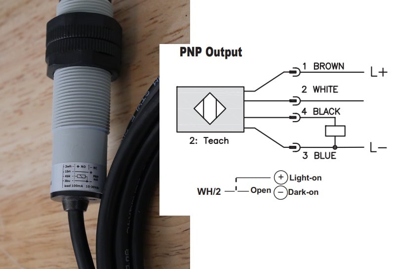
Figure 4. This sensor has a selectable light-on/dark-on mode that uses the white wire. Interestingly, the datasheet diagram (right) calls out light-on and dark-on, but the sensor itself (left) is printed with NO and NC. Image used courtesy of the author
This sensor has four wires: +V, -V, output, and the light-on/dark-on selector. This selector will certainly provide direction to the user as to which output will be provided upon the connection to +V or -V.
With these selectable sensors, it’s actually not essential to use the selector wire. If left unconnected (or entirely clipped off with wire cutters), it will default to whatever output would be provided if the wire was connected to -V.
Optical Sensor Specs
For the most part, optical sensors perform the same functions as most other discrete and analog sensor categories. But this one property (light/dark mode) can cause some confusion for those who haven’t encountered it in the past.